
BUS BAR PROTECTION
Busbars in the generating stations and sub stations form a link between the incoming and outgoing circuits.If a fault occurs in bus bar create damage and disruption of supply.The bus bar faults are generally single line to earth fault and phase to phase fault.
The two most commonly used schemes for busbar protection are
- Differential protection
- Fault bus protection
Differential protection
In differential protection method, currents entering and leaving the bus are totalized. During the normal working condition, the sum of these currents is equal to zero. When a fault occurs, the fault current upsets the balance and produces a differential current to operate a relay.
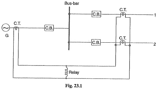
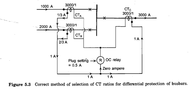
Fig.1 shows the single line diagram of current differential scheme for a station busbar. The busbar is fed by a generator and supplies load to two lines. The secondaries of current transformers in the generator lead, in line 1 and in line 2 are all connected in parallel. The protective relay is connected across this parallel connection. All CTs must be of the same ratio in the scheme regardless of the capacities of the various circuits.
Under normal load conditions or external fault conditions, the sum of the currents entering the bus is equal to those leaving it and no current flows through the relay.
If a fault occurs within the protected zone, the currents entering the bus will not be equal to the current leaving the bus. The difference of these currents will flow through the relay and cause the opening of circuit breakers connected at the end of protected zone
Better understand use below figure
Fault bus protection
Fault bus is an earthed metal barrier that surrounds each conductor throughout its entire length in the bus structure. With this arrangement, every fault on the system can be converted into earth fault.
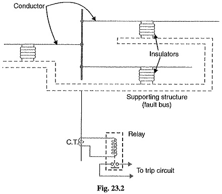
Figure shows the schematic arrangement of fault bus protection. The metal supporting structure or fault bus is earthed through a current transformer. A relay is connected across the secondary of this CT. Under normal operating conditions, there is no current flow from fault bus to ground and the relay does not operate. When a fault occur on the bus bar, a connection between a conductor and earthed supporting structure (fault bus) will result in current flow to ground through the fault bus, causing the relay to operate. The operation of relay will trip all breakers connecting equipment to the bus.


Recent Comments