
Code Converters
CODE CONVERTERS
AIM:
To design and set up the following circuits.
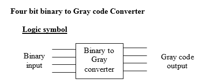
- A four bit binary to gray code converter.
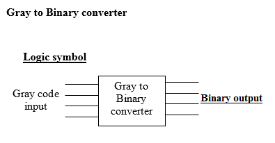
- A four bit Gray to binary code converter.
MATERIALS AND TOOLS REQUIRED:
Digital IC trainer kit, ICs 7486, 7408, Power supply.
THEORY:
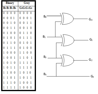
To convert a binary number to corresponding Gray code, the following rules are applied
- The MSB in the Gray code is the same as the corresponding bit in a binary number.
- Going from left to right, add each adjacent pair of binary digits to get the next Gray code digit. Disregard carries.
As the first step to design a binary to Gray code Converter, set up a truth table with binary numbersB3B2B1B0 and corresponding gray code numbers G3G2G1G0. set up a circuit realizing the simplified logic expressions obtained using K maps for Gs as the functions of Bs.
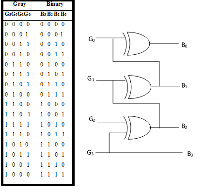
To convert from Gray code to binary, the following rules are applied.
- The most significant digit in the binary number is the same as the corresponding digit in the Gray code
- Add each binary digit generated to the Gray code digit in the next adjacent position. Disregard carries.
To design the Gray to Binary code converter, set up the truth table and get simplified expressions using Karnaugh maps for each binary bits as a function of Gray code bits. Each Gray code number differs from the preceding number by a single bit.
Circuit Diagram:
PROCEDURE:
- Test all the components and IC packages using multimeter and digital IC tester.
- Verify the truth tables of the circuit by feeding the input but combinations.
RESULT:
The following code converters are designed and its truth tables are verified
- A four bit binary to gray code converter
- A four bit Gray to binary code converter


Recent Comments