
Determination of impedance, admittance, power factor of RLC circuit
AIM:
To study the series and parallel RLC circuits & to determine the impedance , admittance , power factor ,active ,reactive and apparent power drawn by the circuit.
APPARATUS REQUIRED:
1.Single phase dimmer- stat 2. Ammeter (AC) 3. Voltmeter (AC) 4. Rheostat 5. Inductor 6.Capacitor 7.Multi Function Meter
RLC SERIES CIRCUIT:
THEORY:
When resistor, inductor and capacitor are connected in series across a voltage supply, the circuit so obtained is called series RLC Circuit.The phasor diagram of series RLC circuit is drawn by combining the phasor diagram of resistor, inductor and capacitor. Before doing so, one should understand the relationship between voltage and current in case of resistor, capacitor and inductor.
PROCEDURE:
- Make the connections as per circuit diagram
- Set the rheostat for maximum resistance.
- Set the dimmer stat to zero output & switch on the mains.
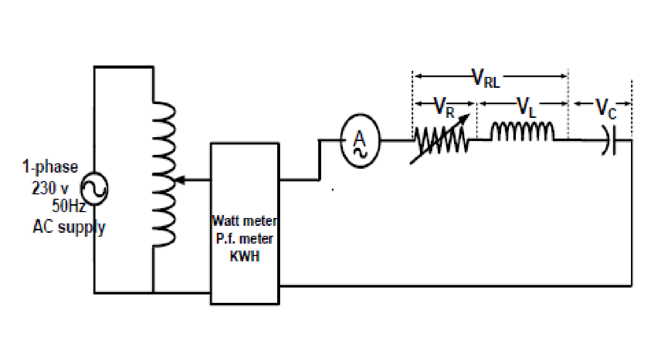
- Adjust the variac so as to apply a suitable voltage to the circuit, measure the current I & voltages VR, VL, Vc, VRL and supply voltage Vs at the output of variac.
- Take different sets of reading by applying different voltage .
- Make the calculations as shown in table. 7. Observe the waveform on CRO.
CIRCUIT DIAGRAM:
OBSERVATION TABLE:
RLC Series circuit :
r , internal resistance of coil = …………
Position of Rheostat | Vs(Volts) | I (Amps) | VR(Volts) | VL(Volts) | VC(Volts) | VRL | PF of the circuit |
Middle position | 100V |
CALCULATIONS – RLC SERIES CIRCUIT:
R = VR/I | ZL = VL/I | XL=√(ZL2 –R2) | Z = Vs/I | Φ from calculationsΦ = Cos-1(R/Z) | Φ from PF meter |
RLC PARALLEL CIRCUIT:
PROCEDURE:
- Make the connections as shown in the circuit diagram.
- Set the Dimmer- stat (variac) to zero output.
- Set the rheostat to maximum.
- Switch on the supply.
- Adjust the variac to give a suitable voltage to the circuit.
- Note down the voltage across R, L, C, & R-L with a.c. voltmeter. Note down the reading of all the meters.
- Take different readings for different another position of rheostat
CIRCUIT DIAGRAM:

OBSERVATION TABLE:
Sl.No | PF of the ckt | Vs(Volts) | I (Amp) | I1(Amp) | I2(Amp) | VR(Volts) | VL(Volts) | VC(Volts) | VRL(Volts) |
Sl.No | R=VR/IRL | XL=VL/IRL | XC=VC/IC | Zeq = Z1 ll Z2Z1 = R+jXLZ2= -jXCZeq = Req+jXeq | Φ from calculationsΦ= Cos-1(Req/Zeq) | Φ from PF meter |
CALCULATIONS:
RESULT:
Studied series and parallel RLC circuits & determined the impedance , admittance , power factor ,active ,reactive and apparent power drawn by the circuit.


Recent Comments