
TRIAC
TRIAC
The major drawback of an SCR is that it can conduct current in one direction only ie, SCR is a unidirectional device, it can conduct from anode to cathode only and not from cathode to anode. Therefore, an SCR can only control DC power on forward bias half cycles of a.c in a load. However in a.c . system .it is often desirable and necessary to exercise control over both positive and negative half cycles. For. This purpose, a semiconductor device called TRIAC is used.
The triac is three terminal device, which can conduct in either direction, when triggered either by a positive or a negative pulse. Irrespective of the polarity of the Voltage across its main terminals. The TRIAC behaves like two SCR s connected in parallel but in opposite direction, with a common gate terminal i.e. the anode of the one SCR is connected to the cathode of the other and their gates are connected together. Thus anode and gate voltage applied in either direction will trigger the TRIAC. It is due to the fact that the applied voltage will trigger atleast one of the SCR connected in opposite direction. The triacs are available with current ratings up to 30 and voltage ratings up to 500 volts.
CONSTRUCTION:
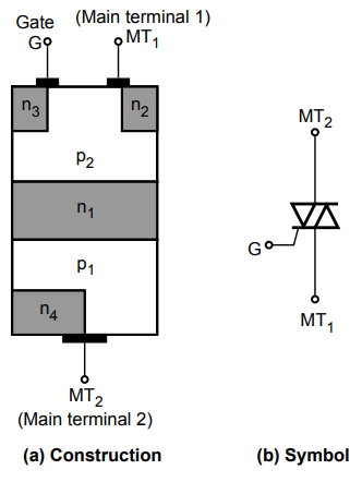
The basic construction of a triac is shown in figure, the triac consists of two four layer switches in parallel. These switches are P 1 N 1 P 2 N 2 and P 2 N1 P 1 N 4. Since The triac conducts in both directions therefore the terminals are designated by numbers instead of anode and cathode as in SCR. The triac has two main terminals namely main terminal 1 i.e.,M.T 1 and maintain terminal 2 i.e.,M.T 2 and one gate terminal (G) fig shows the equivalent circuit of a TRIAC , which consists of two SCRs connected In parallel but in opposite directions with the common gate to terminal .
MODES OF TRIAC TRIGGERING:
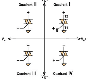
There are four modes of triac operation depending upon the polarity of voltage across the main Terminals and gate in terminal. These modes are described as below .
1 .M.T 2 is positive and G is positive: in this mode, the operation of the TRIAC is identical to SCR. The current flows through the switch P 1 N 1 P 2N 2 from M.T 2 to M.T as shown in fig.
2 M.T.2 is negative and G is positive: In this mode the current flow thought the switch P 2 N 1 P 1 N 4 from M.T 1 to M.T 2. As shown in fig. This is an inefficient mode and must be avoided.
3 M.T.2 is positive and G is negative: in the mode , the current flows through the switch p1 N1 P2N2 from M.T 2 to M.T 1.as shown in fig. This mode is less efficient than mode 1 but not as poor as mode 2.
4 M.T 2. Is negative and G is negative: in this mode the current flows through the switch P2 N1 P1 N4 from M.T 1.to M.T.2 as shown in fig. This mode is slightly less efficient than mode 1.
The MODE 1 and MODE 4 Air efficient modes in triac operation. therefore these two modes there called normal modes triac operation. However as discussed f for the SCR the triac is triggered with the gate pulses of proper polarity of DC voltages. The triac can be turned off. Only by the reducing device current below the holding value of the current.
ADVANTAGES:
- TRIAC needs a single heat sink of slightly larger size.
- TRIAC needs a single fuse for protection which simplifies it’s construction.
- TRIAC Can be triggered with positive or negative polarity voltages.
- In some DC applications the triac may work without a diode as soft breakdown in either direction impossible.
DISADVANTAGES:
- it takes longer time recover to OFF state.
- TRIACs have low dv/dt rating compared with SCRs.
- As TRIAC can be triggered in either direction TRIAC needs careful consideration.
- Reliability of TRIAC is less than that of SCR.


Recent Comments