
IGBT Chopper Control Using 555 Timer
IGBT CHOPPER CONTROL USING 555 TIMER
AIM:
- To study and verify the chopper operation using IGBT triggered by 555 timer. Also obtain the required waveforms and calculate duty cycle of output waveforms.
EQUIPMENTS AND COMPONENTS REQUIRED:
| Sl No | Apparatus/Tool | Specification | Quantity |
| 1 | IGBT | ||
| 2 | 555 Timer | ||
| 3 | Power Supply- | ||
| 4 | Wattage Resistors- | ||
| 5 | Voltmeters- | ||
| 6 | Potentiometers | ||
| 7 | Capacitor | ||
| 8 | SCR, | ||
| 9 | Transformer | ||
| 10 | Bread Board |
THEORY:
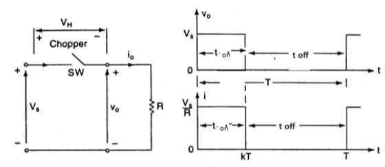
A chopper is a static power electronic device that converts fixed dc input voltage to a variable dc output voltage. A Chopper may be considered as dc equivalent of an ac transformer since they behave in an identical manner.
A chopper is a high speed “on” or “off” semiconductor switch. It connects source to load and load and disconnect the load from source at a fast speed. In this manner, a chopped load voltage as shown in Fig.1 is obtained from a constant dc supply of magnitude Vs. During the period Ton, chopper is on and load voltage is equal to source voltage Vs. During the period Toff, chopper is off, load voltage is zero. In this manner, a chopped dc voltage is produced at the load terminals.
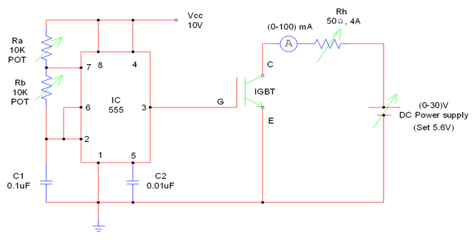
CIRCUIT DIAGRAM:
PROCEDURE:
Set up the 555 firing circuit as per the circuit diagram. Set the POT’s Ra &Rb to the designed values. By using 30V variable power supply, apply 10V to the firing circuit. Check the triggering pulse from pin number 3 of 555 IC. Connect the IGBT circuit with 30V variable power supply in minimum position. Switch on the IGBT power supply and set it to 5.6V then connect the triggering pulse to the gate terminal of IGBT. Verify the output waveform across the load rheostat. Calculate its duty cycle.
RESULT:
Studied and verified the chopper operation using IGBT triggered by 555 timers.


Recent Comments