
Triggering of TRIAC using DIAC
TRIGERING OF TRIAC USING DIAC
AIM:
- To set up a triggering circuit using DIAC for triggering a TRIAC used in a single phase ac phase control circuit.
EQUIPMENTS AND COMPONENTS REQUIRED:
| Sl No | Apparatus/Tool | Specification | Quantity |
| 1 | TRIAC | ||
| 2 | DIAC | ||
| 3 | Power Supply- | ||
| 4 | Wattage Resistors- | ||
| 5 | Voltmeters- | ||
| 6 | Potentiometers | ||
| 7 | Capacitor | ||
| 8 | SCR, | ||
| 9 | Transformer | ||
| 10 | Bread Board |
THEORY:
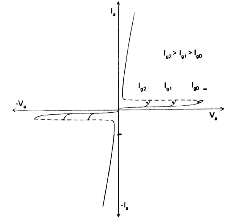
The TRIAC is a bidirectional device with three terminal, two main terminals and a gate. It is a five layer device and is equivalent to a pair of SCR’s connected in anti-parallel. Since the TRIAC can conduct in both directions, the terms anode and cathode are not applicable to the TRIAC. The two main terminals are designated as MT1 and MT2. MT1 is taken as the reference point for measurements of voltage and current at MT2 and gate. The TRIAC is used mainly for the control of power in an circuits. With the gate open, the TRIAC will block both half cycles of ac applied voltage. The TRIAC can be turned on in each half cycle by a negative or positive gate current. So the TRIAC has four triggering modes.
- MT2 positive and gate current positive. The TRIAC operates in the first quadrant.This is called the I+ mode.
- MT2 positive and gate current negative. The TRIAC operates in the first quadrant.This is called the I– mode.
- MT2 negative and gate current positive. The TRIAC operates in the third quadrant.This is called the III+ mode.
- MT2 negative and gate current negative. The TRIAC operates in the third quadrant.This is called the III– mode.
The sensitivity of the TRIAC is maximum in the I+ mode of operation. The TRIAC is least sensitive in the III+ mode of operation and the gate current required to turn on the device is about five times that of I+ mode. So the III+ mode of operation is not commonly used.
The DIAC is a gate less device with two terminals. It is capable of blocking or conducting current in either direction. It is used as trigger device for TRIAC gate circuits.
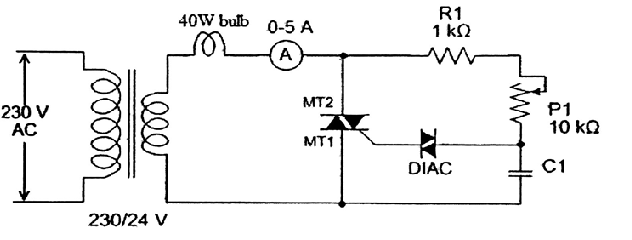
When MT1 is positive with respect to MT2 by a voltage greater than break over voltage, structure P1N1P2N2 breaks over by normal thyristor action. When MT2 is positive with respect to MT2 by a voltage greater than break over voltage, structure P2N1P2N3 breaks down and conducts current. When the device conducts the voltage across it falls to about 3V. The triggering device is a DIAC and the firing angle control is by varying the value of resistance R. during the positive half cycle of the input voltage, capacitor C charges with top plate positive. The charging rate is controlled by the resistance R. when the capacitor voltage, , where VBO is the break over voltage of the DIAC, the TRIAC will trigger, provided the gate current Igt is available. The operation of TRIAC during the positive half cycle is in mode I+. During the negative half cycle, the capacitor charges in the reverse direction and a negative gate signal with respect to MT1 will trigger the TRIAC.
CIRCUIT DIAGRAM:
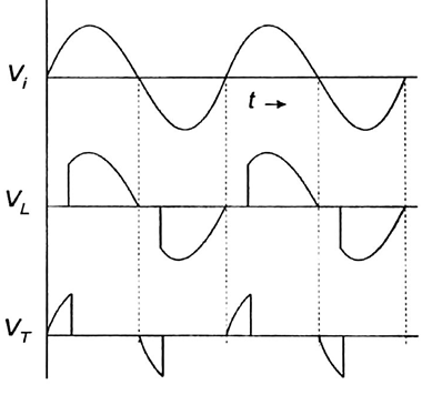
Sample Wave form :
PROCEDURE:
AC phase control circuit using TRIAC is set up. Suitable voltage is applied to the circuit adjusting the autotransformer. Different firing angles are obtained by varying the resistance R, for each firing angle, load voltage, voltage across SCR and DIAC are observed on the CRO.
RESULT:
A single phase voltage controller using TRIAC was set up. The waveforms of source voltage, load voltage, voltage across SCR and voltage across DIAC are observed on the CRO and plotted.


Recent Comments