
Basic Electrical Engineering workshop Lab Manual
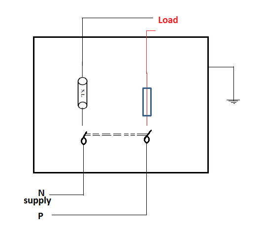
- ASSEMBLING AND TESTING OF A SIMPLE ELECTRIC CIRCUIT.
Aim
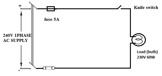
To assemble and test simple electric circuit containing source, knife switch, fuse and a load.
APPARATUS REQUIRED:
| Sl no | Name of Apparatus | Type | Specification | Qty |
| 1 | Fuse unit | Kitkat | 5A,240V | |
| 2 | Load (Bulb) | Clear bulb | 60W,240V | |
| 3 | Knife switch | SPST | 5A,240V | |
| 4 | source | Single phase | 5A,240V |
THEORY:
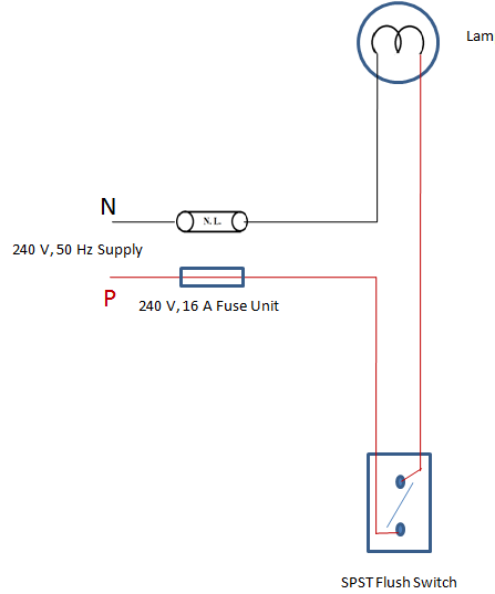
A basic electric circuit contains a source of electric energy, a load which changes electric energy into a useful form of energy and the switch control the energy delivered to the load.
Source: Source is a device which supplies the electrical energy used by the load. It any consists of a simple dry cell, a storage battery or a power supply.
Load: The load is any device through which an electric current flows and which converts their electrical energy into a more useful form.
eg: Bulb, Electric motor etc…..
Switch: It permits control of electrical device, interrupts the current delivered to the load.
The bulb does not glow when switch is open. There is no complete path for current through the circuit. But the switch is closed, the path is complete and current flows from the positive terminal to the negative terminal of the supply. Current will continue to flow until the switch is moved to open position.
PROCEDURE:
Assemble the circuit as shown in the connection diagram .Then the switch is closed and observe the output.
CIRCUIT DIAGRAM
RESULT:
The given circuit is identified. The specification of source, fuse, load, and knife switch are noted.
2 – VOLTAGE AND CURRENT MEASUREMENT USING AMMETER AND VOLTMETER
Aim
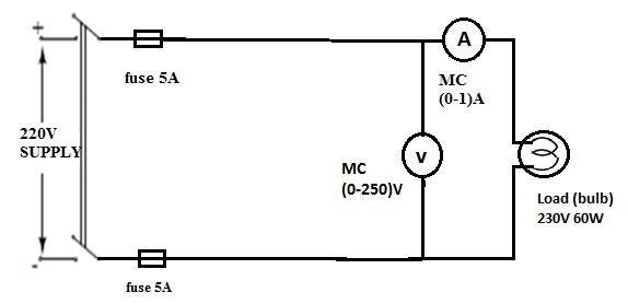
To measure the voltage and current of a given DC circuit.
APPARATUS REQUIRED:
| Sl no | Name of Apparatus | Type | Specification | Qty |
| 1 | Ammeter | |||
| 2 | Voltmeter | |||
| 3 | Lamp | |||
| 4 |
THEORY:
Voltmeter: Voltmeter is always used to measure supply voltage and connected in parallel with supply. If the voltmeter is connected series to the supply it will no reading for DC measurement moving coil type voltmeter and AC measurements used moving iron instruments.
Ammeter: Ammeter is always used to measure supply current and connected in series with the load. It should never be connected in parallel to the supply otherwise it will burn out, for DC measurement Moving Coil type and AC measurements used moving iron instruments.
PROCEDURE
Make the connections as per the connection diagram, switch on the supply, when the lamp will glow note readings of voltmeter and ammeter. Switch off the supply and replace the another lamp, then again note the readings and tabulate.
CIRCUIT DIAGRAM
TABULAR COLUMN
| Sl no. | Lamp | Voltmeter reading (V) | Ammeter reading (A) |
RESULT: The voltage and current of a given circuit is measured with different load.
3- STUDY OF VOLTAGE AND CURRENT MEASUREMENT USING MULTIMETER
Aim
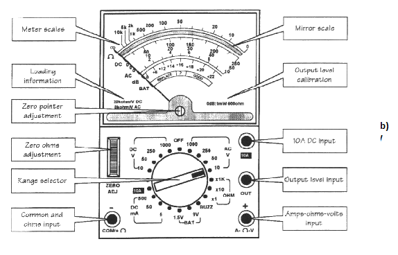
To measure voltage and current using multimeter.
APPARATUS REQUIRED:
Multi meter
THEORY:
Multi meter is used to measure voltage, current and resistance. Therefore it is called AVO Meter. For measuring AC voltage if the range selected switch at the AC select the proper multiplier range. The various voltage ranges are 10V, 55V, 250V, 1000V always start from highest scale.
PROCEDURE:
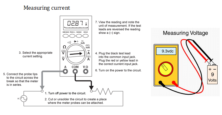
- DC is polarity sensitive; it required to connect with proper terminals. The multi meter leads are colour coded red and black.
- Connect the red lead to the positive and black to negative.
- While taking measurement on receiver, click the black lead to the chassis red lead to the point. Where measurement are to be noted. For DC current measurement procedure is same and DC voltage measurement and DC current measurement multi meter is connected in series. If the range selected switch at the DC current range.
- The various DC current ranges are 10Ma, 100Ma, 250Ma, and 1A on the multi meter.
- Check the main voltage of domestic supply with the help of multi meter; It should be 220 – 230V.
RESULT: In the given circuit the voltage and current are studied in the given multi meter.
MULTIMETER DIAGRAM
4 – RESISTANCE MEASUREMENT (COLOUR CODING)
Aim
- To identify resistor value and tolerance from the colour code and multimeter reading.
- To compare colour coded resistor value with the actual measured resistor value (by multimeter).
APPARATUS REQUIRED:
| Sl no | Name of Apparatus | Type | Specification | Qty |
| 1 | Resistor | |||
| 2 | Multimeter | |||
THEORY:
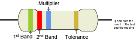
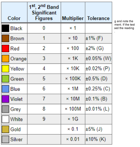
Since it is not practical to print the resistance value on the resistors due to its small size, there for a method called colour code is adopted. The resistance values are generally printed on the body of bigger resistors like wire wound and metal film like resistor. But for the carbon resistor the values are colour coded since its size is very small to print. The value directly on the body of resistors. Colour coding is standardization by electronic industry association (EIA) colour bands are marked on the surface on the resistors. From one end the first band gives the first significant digit, second value gives the second significant digit of the resistance value and third band gives the multiplier and fourth band represents the tolerance in percentage value.
PROCEDURE:
Using colour code:
- Hold the resistor so that the colour bands are in the left end of the resistor. Write down the numeric value of the first colour band.
- Write down the numerical value of the second colour band at the right side of the first numeric.
- Read the numeric value of the third colour band and write down those many zeros at the right side of the second numeric.
- Repeat the procedures for various resistors.
Using multimeter:
- Keep the range selector switch to its suitable position shown in the multimeter load. Adjust the zero with the help of zero ohm adjuster.
- Connect the two end of resistor to the multimeter the pointer will deflect towards the right and stop after takes the reading.
- Compare the value with the colour code value.
CIRCUIT DIAGRAM
TABULAR COLUMN
| Sl no. | Colour band | Resistance using colour code | Resistance using multimeter |
RESULT:
Identified the resistance value and the tolerance from the colour code, and compared it will the multi meter measurement.
5 – CABLE IDENTIFICATION
Aim
To measure the gauge and the area of the cross section of a given wire with the type of a standard wire gauge.
MATERIALS REQUIRED:
Given piece of wire, wire stripper, standard wire gauge (SWG) and cotton waste.
PROCEDURE:
- If the wire is PVC, VIR, CTS, remove about 4 cm of insulation. Remove all foreign material from the end of the wire to be measured. If it is standard wire, take only one of the strands and clean it with cotton waste.
- Place the bare conductor in the slot of wire gauge. Keep testing the wire in various slots until it fits easily in one the of them. Read the gauge number of the slot on the phase of the wire gauge in which bare conductor fix easily. This is the required gauge number of the wire.
PRECAUTIONS:
- Cutting insulation like minding a pencil so that there should not be cut on the conductor.
- Sand paper should not be used on the wire. The wire will be become thin, use cotton to clean.
- The bare conductor should not be loose or tight enough in this slot for standard wire, take only one strand.
CIRCUIT DIAGRAM
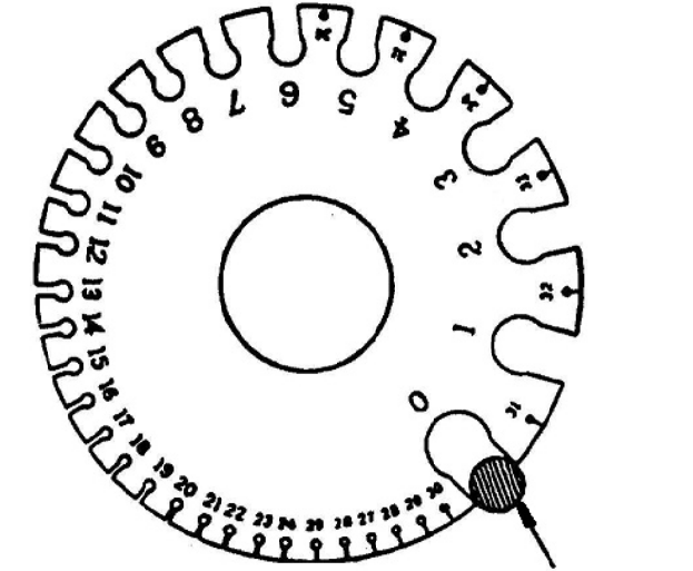
Wire gauge
RESULT:
Identified the given wire gauge and area of cross section and measured.
6 – SYMBOL IDENTIFICATION
Aim
To verify the status of the following features.
- SPST
- SPDT
- DPST
- Push to on switch
- Push to off switch
APPARATUS REQUIRED:
| Sl no | Name of Apparatus | Type | Specification | Qty |
| 1 | Fuse | |||
| 2 | Round block | |||
| 3 | Lamp | |||
PROCEDURE:
- Place round block in the place of lamp and switch using two good screws.
- Fix the kit Kat fuse using two screws.
- Cut wires according to the length given in the layout.
- Connect the wire in the terminals after skin the joints should be tight.
- After completing the circuit checks it and gives supply.
- Test whether you get the conditions and disconnected.
CIRCUIT DIAGRAM
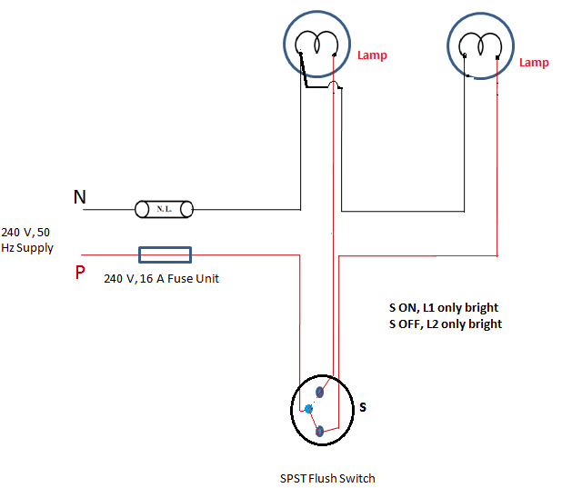
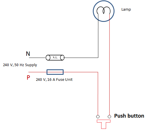
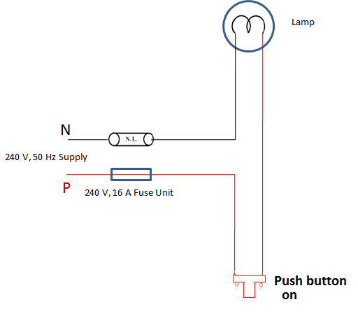
RESULT:
The given circuit is studied, and the symbols are identified.
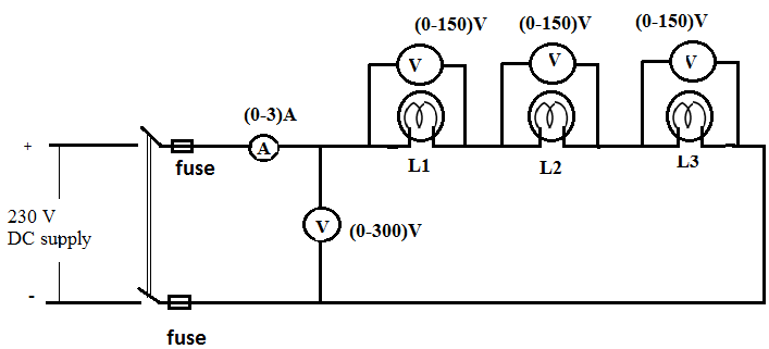
7 – VOLTAGE AND CURRENT MEASUREMENT IN SERIES COMBINATION
Aim
To determine,
- Voltage
- Current and value of resistance in series combination.
APPARATUS REQUIRED:
| Sl no | Name of Apparatus | Type | Specification | Qty |
| 1 | Voltmeter | |||
| 2 | Ammeter | |||
| 3 | Rheostat | |||
| 4 | Lamp |
THEORY:
- In series circuit, supply voltage will be equal to sum of the voltage drop across each resistance.
- Current same in the entire element in the circuit.
- Drop in volts depends on the value of resistance of each.
- Total resistance is equal to the sum of resistance connected.
PROCEDURE:
- Connect the accessories as per the diagram.
- Close the circuit and note the readings of voltmeter across each lamp and the supply voltage, also note the current.
- Repeat the experiment by changing wattage of each bulb.
- Tabulate the readings.
CIRCUIT DIAGRAM
TABULAR COLUMN
| Sl no. | L1 | L2 | L3 | I | V1 | V2 | V3 | Total= V1+V2+V3 | R1=V1/I | R2=V2/I | R3=V3/I | R=V/I | Total resistance R=R1+R2+R3 |
RESULT:
The given circuit is set up and voltage across each resistance and current is measured.
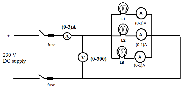
8-VOLTAGE AND CURRENT MEASUREMENT IN PARALLEL COMBINATION
Aim
To study its circuit relation,
- Current relation
- Voltage relation
- Value of resistance in the circuit.
APPARATUS REQUIRED:
| Sl no | Name of Apparatus | Type | Specification | Qty |
| 1 | Voltmeter | |||
| 2 | Ammeter | |||
| 3 | Rheostat | |||
| 4 | Lamp |
THEORY:
- In parallel circuit, sum of the branch current is equal to the total current.
- Voltage across each resistance is same in the entire element in the circuit.
- Total resistance decreases with increased number of resistance in parallel and hence current also increases.
- Circuit is not interrupted if there is any interruption in the branch.
PROCEDURE:
- Connect the accessories as per the diagram.
- Close the circuit and note the readings of voltmeter across each lamp and the supply voltage, also note the current.
- Repeat the experiment by changing wattage of each bulb.
- Tabulate the readings.
CIRCUIT DIAGRAM
TABULAR COLUMN
| Sl no. | L1 | L2 | L3 | V | I | I1 | I2 | I3 | Total I= I1+I2+I3 | R1=V/I1 | R2=V/I2 | R3=V/I3 | R=V/I | Total resistance R=R1+R2+R3 |
RESULT: The given circuit is set up and current across each resistance and voltage is measured.
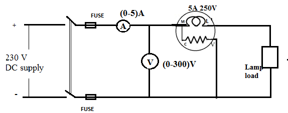
9 – POWER MEASUREMENT IN DC CIRCUIT
Aim
To connect and take the readings of wattmeter.
APPARATUS REQUIRED:
| Sl no | Name of Apparatus | Type | Specification | Qty |
| 1 | Wattmeter | |||
| 2 | Lamp load | |||
| 3 | Ammeter | |||
| 4 | Voltmeter |
PROCEDURE:
- Connections are made as per the connection diagram.
- Connect the wattmeter as current coil in series and pressure coil across the line.
- Connect the voltmeter and ammeter for verification of wattmeter reading.
- Tabulate the readings carefully for different load.
CIRCUIT DIAGRAM
TABULAR COLUMN
| Sl no. | Wattmeter reading (W)X2 | Voltage applied to the load (V) | Ammeter reading (A) | P= V XI |
RESULT:
The given circuit is studied; the power measurement an DC circuit is verified.
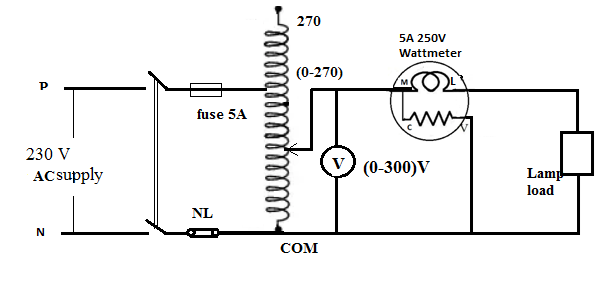
10 – SINGLE PHASE ENERGY MEASUREMENT USING ENERGY METER
Aim
To measure single phase energy consumed by a load use of energy meter.
APPARATUS REQUIRED:
| Sl no | Name of Apparatus | Type | Specification | Qty |
| 1 | Wattmeter | |||
| 2 | Lamp | |||
| 3 | Fuse | |||
| 4 | Voltmeter | |||
| 5 | Neutral link |
THEORY:
Let the time taken for ‘n’ revolution of the energy meter‘t’ second
No of revolutions per hours = n/ (t/3600)
Energy consumed by the load = (n x 3600)/ (t x k)
Where k is equal to energy meter constant in revolution per KWH
PROCEDURE:
- Connections are made as per the connection diagram.
- Before switch on the supply the auto transformer must be in the minimum position and the loads are in off position.
- Now switch on the single phase AC supply adjust the auto transformer so that the voltmeter reading 230 V.
- Now insert the lamp load take the time taken for n revolution of the energy meter disc using stop watch.
CIRCUIT DIAGRAM
TABULAR COLUMN
| Sl no. | Voltage in V | Time for 5 revolves of energy meter rev. in sec | Energy consumed by the load=nx3600/t x k in KWH |
RESULT:
The given circuit is studied and single phase energy is measured using the energy meter.


Recent Comments