
Bridge Rectifier Lab Manual
Full Wave Rectifier (Bridge Rectifier)
Aim :
To study the characteristics of Full wave Bridge rectifier with and without filter and calculate its ripple factor.
Components and equipments required:
- Diode 1N4007 4no
- Resistor 1K 1no
- Step down transformer 6-0-6 1no
- Breadboard, CRO, BNC probe, connecting wires etc….
Theory :
In a bridge configuration, the number of rectifier elements used is same as that used in full wave rectifier with centre tap.The principal features of bridge rectifier is
- Current in both the primary and secondary of the supply transformer flows for the entire ac cycle and hence for a given power output, power transformer of a smaller size is used in comparison with that of full wave rectifier.
- No centre tap is needed in the transformer secondary.
- Since two diodes are present in series in each conduction path, the peak inverse voltage is shared equally by the two diodes. Peak inverse voltage is Vm
Hence bridge rectifier is used for high voltage applications.
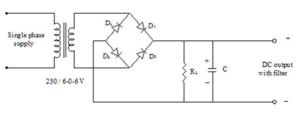
The output of full wave rectifier is pulsating, it has a dc value of magnitude 2Vm/π and some AC variations called ripples. Certain circuits need very smooth dc voltage. Hence the circuits that converts a pulsating output from a rectifier to a very steady dc level is known as filter, because it filters out or smoothens out pulsations in the output. Here a capacitor of suitable value C1 connected across the rectifier and in parallel with the load RL to achieve filtering action. This filter circuit depends on a property of capacitor that it opposes any change in voltage across its terminals. When connected across a pulsating DC voltage, it tends to smoothen out or filter out the voltage pulsations.
Procedure:
- The circuit is wired as in the circuit diagram.
- Connect the supply voltage to the primary of the transformer.
- Connect the output terminals to the CRO and observe the input output waveform.
- Measure the dc voltage at the input and output points.
- Measure the dc voltage across the load resistor.
- Calculate the ripple factor, dc output voltage.
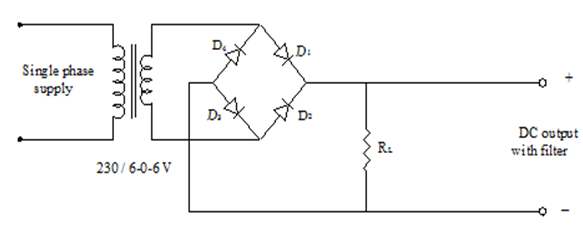
Circuit Diagram
Bridge Rectifier without Filter
Bridge Rectifier with Filter
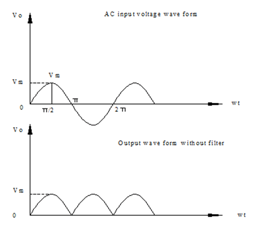
Sample Graph:
Result :
Ripple factor , r =…….. (with filter)


Recent Comments