
Construction of DC Generator
An electric generator is a machine that converts mechanical energy into electrical energy. An electric generator is based on the principle that whenever flux is cut by a conductor, an e.m.f. is induced which will cause a current to flow if the conductor circuit is closed.The direction of induced e.m.f. (and hence current) is given by Fleming’s right hand rule.
It mainly consists of three main parts, i.e. magnetic field system, armature and commutator and brush gear. The other parts of a DC Generator are magnetic frame and yoke, pole core and pole shoes, field or exciting coils, armature core and winding’s, brushes, end housings, bearings and shafts.
Construction of d.c. Generator:
All d.c. machines have five principal components are,
(i)field system:
- The Magnetic Field System is the stationary or fixed part of the machine. It produces the main magnetic flux. The magnetic field system consists of Mainframe or Yoke, Pole core and Pole shoes and Field or Exciting coils.
- Function of the field system is to produce uniform magnetic field within which the armature rotates, It Consists of a number of salient poles (even number) bolted to the inside of circular frame (generally called yoke).
- Yoke is usually made of cast steel or rolled steel for the large machines and for the smaller size machine the yoke is generally made of cast iron. whereas the pole pieces are composed of stacked lamination’s.
- Function of Yoke: It supports the pole cores and provides mechanical protection to the inner parts of the machines & It provides a low reluctance path for the magnetic flux.
- The Pole Core and Pole Shoes are fixed to the magnetic frame or yoke by bolts. The poles are laminated to reduce the Eddy Current loss.Field coils are mounted on the poles and carry the d.c.exciting current.The field coils are connected in such a way that adjacent poles have opposite polarity.
- The poles core serves, It supports the field or exciting coils & They spread out the magnetic flux over the armature periphery more uniformly.
- Each pole core has one or more field coils (windings) placed over it to produce a magnetic field. The enamelled copper wire is used for the construction of field or exciting coils. By reducing the length of air gap, we can reduce the size of field coils.
- MMF developed by the field coils produces a magnetic flux that passes through the pole pieces, the air gap, the armature and the frame.
- Practical d.c. machines have air gaps ranging from 0.5 mm to 1.5 mm.
- Armature and field systems are composed of materials that have high Permeability.
(ii) armature core:
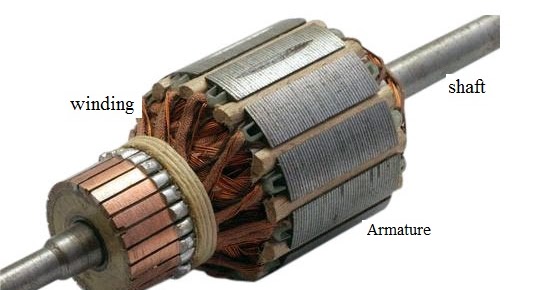
- The armature core of DC Generator is cylindrical in shape and keyed to the rotating shaft and rotates between the field poles.
- It consists of slotted soft-iron lamination’s (about 0.4 to 0.6 mm thick) that are stacked to form a cylindrical core.
- The lamination’s are individually coated with a thin insulating film so that they do not come in electrical contact with each other.The purpose of laminating the core is to reduce the eddy current loss.
- The lamination are slotted to accommodate and provide mechanical security to the armature winding and to give shorter air gap for the flux to cross between the pole face and the armature“teeth”.
(iii) armature winding:
- The slots of the armature core hold insulated conductors that are connected in a suitable manner known as armature winding. The insulated conductors are placed in the slots of the armature core. The conductors are wedged, and bands of steel wire wound around the core and are suitably connected.
- This is the winding in which “working” e.m.f. is induced.
- The armature conductors are connected in series-parallel; the conductors being connected in series so as to increase the voltage and in parallel paths so as to increase the current.
(iv) commutator:
- A commutator is a mechanical rectifier which converts the alternating voltage generated in the armature winding into direct voltage across the brushes.
- The commutator is made of copper segments insulated from each other by mica sheets and mounted on the shaft of the machine.
- The segments form a ring around the shaft of the armature. Each commutator segment is connected to the ends of the armature coils.
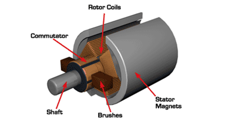
(v) brushes
- The purpose of brushes is to ensure electrical connections between the rotating commutator and stationary external load circuit.The brushes are pressed upon the commutator and form the connecting link between the armature winding and the external circuit.
- The brushes are made of carbon and rest on the commutator.
- The brush pressure is adjusted by means of adjustable springs.


Recent Comments