
Working Principle of DC Generator
Working Principle:
An electric generator is based on the principle that whenever flux is cut by a conductor, an e.m.f. is induced which will cause a current to flow if the conductor circuit is closed.The direction of induced e.m.f. (and hence current) is given by Fleming’s right hand rule.
A DC generator produces direct power, while an AC generator produces alternating power.

Simple Loop Generator:
- Consider a single turn loop ABCD rotating clockwise in a uniform magnetic field with a constant speed.
- As the loop rotates, the flux linking the coil sides AB and CD changes continuously.Hence the e.m.f. induced in these coil sides also changes but the e.m.f. induced in one coil side adds to that induced in the other.
- (i) When the loop is in position no. 1 the generated e.m.f. is zero because the coil sides (AB and CD) are cutting no flux but are moving parallel to it.
- (ii) When the loop is in position no. 2, the coil sides are moving at an angle to the flux and, therefore, a low e.m.f. is generated as indicated by point 2.
- (iii) When the loop is in position no. 3, the coil sides (AB and CD) are at right angle to the flux and are, therefore, cutting the flux at a maximum rate.
- Hence at this instant, the generated e.m.f. is maximum as indicated by point 3.(iv) At position 4, the generated e.m.f. is less because the coil sides are cutting the flux at an angle.
- (v) At position 5, no magnetic lines are cut and hence induced e.m.f. is zero as indicated by point 5.
- (vi) At position 6, the coil sides move under a pole of opposite polarity and hence the direction of generated e.m.f. is reversed.
- (vii) The maximum e.m.f. in this direction (i.e., reverse direction, will be when the loop is at position 7 and zero when at position 1.
- This cycle repeats with each revolution of the coil.
- If a load is connected across the ends of the loop, then alternating current will flow through the load.
commutator
- The alternating voltage generated in the loop can be converted into direct voltage by a device called commutator.
- In commutator, If the connection of the coil side to the external load is reversed at the same instant the current in the coil side reverses, the current through the load will be direct current.
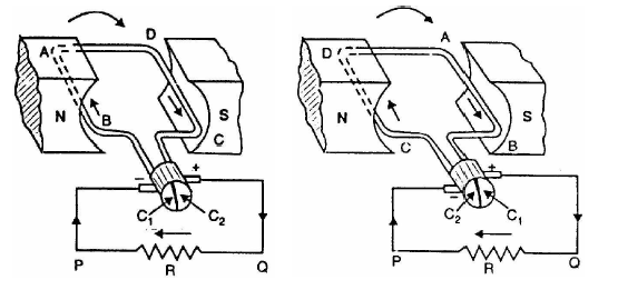
- It consists of a cylindrical metal ring cut into two halves or segments C1 and C2 respectively separated by a thin sheet of mica. The commutator is mounted on but insulated from the rotor shaft. The ends of coil sides AB and CD are connected to the segments C1 and C2 respectively. With this arrangement, the commutator at all times connects the coil side under S-pole to the +ve brush and that under N-pole to the -ve brush.Here the coil sides AB and CD are under N-pole and S-pole respectively.
- Note that segment C1 connects the coil side AB to point P of the load resistance R and the segment C2 connects the coil side CD to point Q of the load.
- After half a revolution of the loop (i.e., 180° rotation), the coil side AB is under S-pole and the coil side CD under N-pole. The currents in the coil sides now flow in the reverse direction but the segments C1 and C2 have also moved through 180° i.e., segment C1 is now in contact with +ve brush and segment C2 in contact with -ve brush. Sothe commutator has reversed the coil connections to the load i.e.,coil side AB is now connected to point Q of the load and coil side CD to the point P of the load. Also note the direction of current through the load.
Brushes:
- Two stationary carbon brushes rest on the commutator and lead current to the external load. alternating voltage generated in the loop will appear as direct voltage across the brushes.The purpose of brushes is simply to lead current from the rotating loop or winding to the external stationary load.


Recent Comments