
Distance /Impedance relay
Relay Operation is governed by the ratio of applied voltage to current in the protected circuit. ie,the relay operates depending upon the impedance between the point of fault and the point where relay is installed. Such relay called distance or impedance relay.relay which functions depending upon the distance of fault in the line.
The operation of such relay depends upon the predetermined value of voltage to current ratio.ie, impedance. The relay will only operate when this voltage to current ratio becomes less than its predetermined value. As the impedance of a transmission line is directly proportional to its length, it can easily be concluded that a distance relay can only operate if fault is occurred within a predetermined distance or length of line.
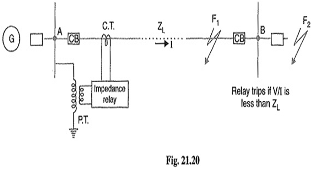
The voltage element of the relay is excited through a potential transformer (P.T.) from the line to be protected. The current element of the relay is excited from a current transformer (C.T.) in series with the line. The portion AB of the line is the protected zone.. Under normal operating conditions, the impedance of the protected zone is Z L. The relay is so designed that it closes its contacts whenever impedance of the protected section falls below the pre-determined value i.e.Z L in this case.
Now suppose a fault occurs at point F1 in the protected zone. The impedance Z (=V/I) between the point where the relay is installed and the point of fault will be less than Z L and hence the relay operates. Should the fault occur beyond the protected zone (say point F2), the impedance Z will be greater than ZL and the relay does not operate.
Types of Distance Relays or Impedance Relays:
- Definite-Distance relay : which operates instantaneously for fault up to a pre-determined distance from the relay.
- Time-Distance relay : which the time of operation is proportional to the distance of fault from the relay point. A fault nearer to the relay will operate it earlier than a fault farther away from the relay.
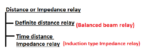
1.Definite Distance Type Impedance Relay / Balanced beam relay
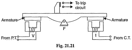
It consists of a pivoted beam F and two electromagnets energized respectively by a current and voltage transformer in the protected circuit. The armatures of the two electromagnets are mechanically coupled to the beam on the opposite sides of the fulcrum. The beam is provided with a bridging piece for the trip contacts. The relay is so designed that the torques produced by the two electromagnets are in the opposite direction.
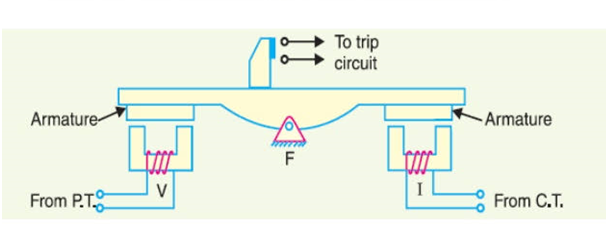
Operation: Under normal operating conditions of this Definite Distance Type Impedance Relay, the pull due to the voltage element is greater than that of the current element. Therefore, the relay contacts remain open. However, when a fault occurs in the protected zone, the applied voltage to the relay decreases whereas the current increases. The ratio of voltage to current (i.e. impedance) falls below the pre-determined value. Therefore, the pull of the current element will exceed that due to the voltage element and this causes the beam to tilt in a direction to close the trip contacts.
The pull of the current element is proportional to I2 and that of voltage element to V2. Consequently, the relay will operate when,
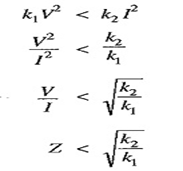
The value of the constants k1 and k2 depends upon the ampere-turns of the two electromagnets. By providing tappings on the coils, the setting value of the relay can be changed.
Time Distance Impedance Relay/Induction Type Impedance Relay
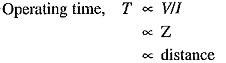
A time-distance impedance relay is one which automatically adjusts its operating time according to the distance of the relay from the fault point i.e.
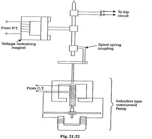
Construction: Fig shows the schematic arrangement of a typical induction type time-distance impedance relay. It consists of a current driven induction element similar to the double-winding type induction over current relay. The spindle carrying the disc of this element is connected by means of a spiral spring coupling to a second spindle which carries the bridging piece of the relay trip contacts. The bridge is normally held in the open position by an armature held against the pole face of an electromagnet excited by the voltage of the circuit to be protected.
Operation: Under normal load conditions, the pull of the armature is more than that of the induction element and hence the trip circuit contacts remain open. However, on the occurrence of a short-circuit, the disc of the induction current element starts to rotate at a speed depending upon the operating current. As the rotation of the disc proceeds, the spiral spring coupling is wound up till the tension of the spring is sufficient to pull the armature away from the pole face of the voltage-excited magnet. Immediately this occurs, the spindle carrying the armature and bridging piece moves rapidly in response to the tension of the spring and trip contacts are closed. This opens the circuit breaker to isolate the faulty section.
The speed of rotation of the disc is approximately proportional to the operating current, neglecting the effect of control spring. Also the time of operation of the relay is directly proportional to the pull of the voltage-excited magnet and hence to the line voltage V at the point where the relay is connected. Therefore, the time of operation of relay would vary as V/I i.e. as Z or distance.


Recent Comments