
PROTECTIVE RELAYS
A protective relay is a device that detects the fault and initiates the operation of the circuit breaker to isolate the defective element from the rest of the system.
The relay detects the abnormal conditions in electrical circuits by constantly measuring the electrical quantities which are different under normal and faulted conditions. the electrical quantities which may change under fault conditions are voltage, current, frequency.. after detecting the fault the relay operates to complete the trip circuit which results in the opening of the circuit breaker and disconnection of the faulty circuit. A typical relay circuit shown in fig
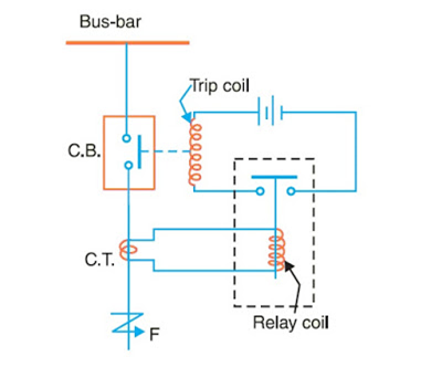
- Mainly it consists of a fixed contact and movable sliding contact, called electrodes following a relay circuit and tripping circuit
- Relay circuit for detects the faults and supplies information to the breaker for circuit interruption.It consists of a Current transformer and a tripping circuit.
- Current transformer : primary winding of CT is connected in series with the circuit to be protected and secondary of CT connected the relay operating movable contact.
- Tripping coil : It contains a source of supply, trip coil of circuit breaker and relay stationary contacts.
Working
Under Normal condition : The emf of the secondary winding of a Current transformer is small, and the current flowing in the relay operating coil is insufficient to close the relay contacts. This keep the trip coil of the circuit breaker unenergized. ie, the circuit breaker movable contacts is in closed position under normal conditions.
Faulted Condition: When a fault occurs, a large current flows through the primary winding of CT, This increase the secondary emf & hence the current through the relay operating coil. The relay contacts are closed and the trip coil of the breaker is energized to open the contacts of the circuit breaker.
When the contacts of the CB are operated under fault condition, an arc is struck between them. Thus the current is able to continue until the discharge ceases. The production of arc not only delays the current interruption but also generates enormous heat which may cause damage the system. ie, main problem in a CB is extinguish the arc within the shortest possible time so that heat generated by it may not reach a dangerous value.
Fundamental requirement of Protective Relay
- Selectivity: It is the ability of the system to select correctly that part of the system in trouble and disconnect the faulty part without disturbing the rest of the system.
- Sensitivity: ability of the system to operate with low value of actuating current.
- Reliability: It is the ability of the Protective Relay system to operate under the pre-determined conditions. Without reliability, the protection would be rendered largely ineffective and could even become a liability.
- Simplicity: The relaying system should be simple so that it can be easily maintained. Reliability is closely related to simplicity.
- Economical: The most important factor in the choice of a particular protection scheme is the economic aspect.
- Speed: The relay system should disconnect the faulty section as fast as possible. The relay system should disconnect the faulty section as fast as possible for the following reasons,
- Electrical apparatus may be damaged if they are made to carry the fault currents for a long time.
- A failure on the system leads to a great reduction in the system voltage. If the faulty section is not disconnected quickly, then the low voltage created by the fault may shut down consumers motors and the generators on the system may become unstable.
- The high speed relay system decreases the possibility of development of one type of fault into the other more severe type.
Basic Relays
Most of the protective relays in service on electric power system today are of electro-mechanical type. They work on the following two main principles,
- Electromagnetic attraction
- Electromagnetic induction
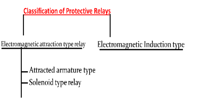
Electromagnetic attraction Relays:
Electromagnetic relays are those relay which operates on the principle of electromagnetic attraction. It is a type of a magnetic switch which uses the magnet for creating a magnetic field. The magnetic field then uses for opening and closing the switch and for performing the mechanical operation.
1. Attracted armature type relay:
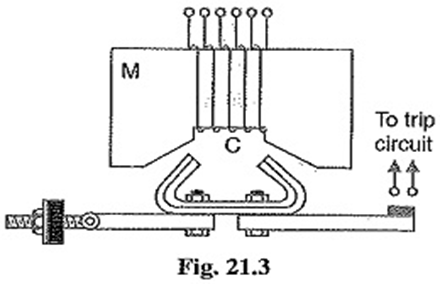
In this relay, the armature is attracted to the pole of a magnet. The electromagnetic force exerted on the moving element is proportional to the square of the current flow through the coil. This relay responds to both the alternating and direct current.
In this relay, the armature is attracted to the pole of a magnet. The electromagnetic force exerted on the moving element is proportional to the square of the current flow through the coil. This relay responds to both the alternating and direct current.
It consists of electromagnet M carrying a coil C and a pivoted laminated armature. The armature is balanced by a counter weight and carries a pair of spring contact fingers at its end. Normal operating conditions, the current through the relay coil C is such that counter weight holds the armature in the position shown in figure. When a short circuit occurs, the current through the relay coil increases sufficiently and the relay armature is attracted upwards. The contacts on the relay armature bridge a pair of stationary contacts attached to the relay frame. This completes the trip circuit which results in the opening of the circuit breaker and there fore in the disconnection of the faulty circuit.
2. Solenoid type relay:
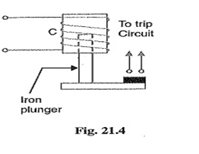
It consists of a solenoid and a movable iron plunger arranged as shown. Under normal operating conditions, the current through the relay coil C is such that it holds the plunger by gravity or spring in the position shown. However, on the occurrence of a fault, the current through relay coil becomes more than the pick up value, causing the plunger to be attracted to the solenoid. The upward movement of the plunger closes the trip circuit, thus opening the circuit breaker and disconnecting the circuit breaker and disconnecting the faulty circuit..
Electromagnetic induction type relays
Electromagnetic-induction relays use the principle of the induction motor where torque is developed by induction in a rotor; this operating principle applies only to relays actuated by Alternating Current, and called Induction Type relays.Induction-type relays are the most widely used for protective-relaying purposes involving AC quantities.
An Induction Type Relay essentially consists of a pivoted aluminium disc placed in two alternating magnetic fields of the same frequency but displaced in time and space. Actuating force is developed in a movable element that may be a disc or other form of rotor of non-magnetic current-conducting material by the interaction of electromagnetic fluxes with eddy currents that are induced in the rotor by these fluxes.
In Induction Relay Torque Equation, Two magnetic fluxes Φ1 and Φ2 differing in time phase penetrate through a disc. These alternating fluxes induce emfs e1 and e2 in the disc which lag their respective fluxes by 90°. These emfs lead to the flow of eddy currents i1 and i2. By the interaction of Φ1 with i2 and Φ2 with i1 a driving torque is produced.

ɸ1 = ɸ1max sin ωt
ɸ2 = ɸ2max sin (ωt + θ)
where, θ is the angle by which ɸ2 leads ɸ1
Assume that rotor current flow have negligible self-inductance, and therefore rotor currents are in phase with their respective induced voltages.
Now-
i1 ∝ e1 ∝ d ɸ1/dt ∝ ɸ1max cos ωt
i2 ∝ e2 ∝ d ɸ2/dt ∝ ɸ2max cos (ωt + θ)
F1∝ ɸ1i2 & F2∝ ɸ2i1
Since the two forces (F1 and F2) developed are in opposition, as illustrated in Fig, therefore net force acting on the movable element is given as –
F = (F2 – F1) ∝ ɸ2 i1 – ɸ1 i2
∝ ɸ1max ɸ2max [cos ωt sin (ωt + θ) – sin ωt cos (ωt + θ)]
F ∝ ɸ1max ɸ2max sin θ …
The greater the phase angle 0 between the two fluxes, the greater is the net force applied to the disc.
Types of Induction relays
- Watt hour meter type
- Shaded pole structure
- Induction cup structure
Watt hour meter / double winding structure
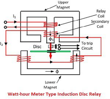
It consists of a pivoted aluminium disc arranged to rotate freely between the poles of the electromagnets. the upper magnet carries two windings, the primary and secondary. the primary winding carries the relay current I1 while the secondary winding is connected to the windings of lower magnet. the primary current induces emf in the secondary by transformer action and so circulates a current I2 in it.flux ɸ2 induced in the lower magnet by the current in the secondary windings of upper magnet will lag behind ɸ1 by an angle θ.Actuating force is developed in a movable element by the interaction of electromagnetic fluxes with eddy currents that are induced in the rotor by these fluxes.
The driving torque on the disc ∝ ɸ1max ɸ2max sin θ


Recent Comments