
Electrical Power Utilisation & System protection
I Unit – FUSES & CIRCUIT BREAKERS
1.Define Fuse?
A fuse is a safety device, used for the purpose of protecting a circuit against excess current(overload/short circuit condition).
It is a short piece of metal inserted in series with the circuit, which melts when excessive current flows through it and thus breaks the circuit.
2. Name the alloy of materials for fuse element having small current ratings?
Alloy of Tin & Lead (63% & 37%)
3. Write any two desirable Characteristics of Fuse element?
- Low melting point ( like tin & lead)
- High conductivity (like silver & copper..)
- Free from deterioration due to oxidation ( silver..)
- Low cost (eg: lead, tin , copper..)
4. Define the terms: i) Fuse element ii)Current rating of fuse element iii) Fusing current iv) Fusing factor?
i) Fuse element /Fuse Wire : It is that part of the fuse which melts when an excessive current flows in the circuit, and thus isolates the device from the supply mains.
ii)Current rating of fuse element : It is the maximum current that can pass continuously without over heating or melting.
iii) Fusing Current : It is the minimum current at which the fuse element melts & thus disconnects the circuit protected by it.
Its value will be more than the current rating of fuse element.
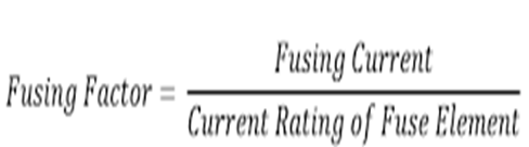
iv) Fusing Factor : It is the ratio of minimum fusing current to the current rating of fuse element.
5. List the Factors affecting Current carrying capacity of fuse element?
- Nature of the material used
- Ambient temperature
- Length of fuse wire : Fuse of small length the heat is easily conducted away to the terminals., so the fuse can carry more current
- Diameter
- Size & location of terminals used : (Bigger size will dissipate more heat)
- The state of the surface of fuse wire : (Stranded fuse will carry less current)
- Nature of the sorroundings : ( Oxidation : The fusing elements of the fuse are exposed to air, hence it is oxidized. Therefore the resistance of the element is increased and produced heat when the current passing through it….)
6.Define fusing factor ?
It is the ratio of minimum fusing current to the current rating of fuse element.
Its value is always more than one. smaller fusing factor means the greater is the difficulty in avoiding deterioration due to over heating & oxidation at rated carrying current.
Fusing factor = Fusing current / current rating of fuse element
7. Describe the Inverse Current Characteristics of a Fuse?
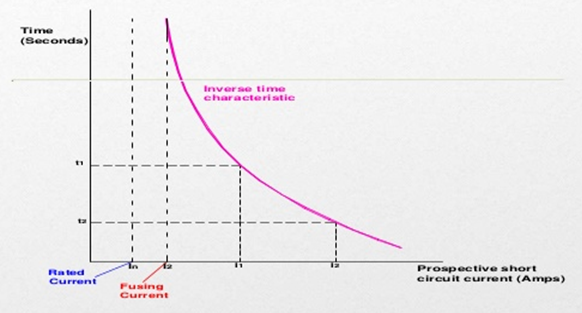
The fuse has inverse time current characteristics ie, if the short circuit current is high, time taken to interrupt is low and vice versa happens when the fault current is low.. Time required to blow out the fuse depends upon the magnitude of fault current (short circuit / over loaded ) . Th greater the current, smaller the time taken by the fuse to blow out.
8. Explain the Advantage & disadvantages of Fuse?
- Advantages :
- Fuse is cheapest type of protection in an electrical circuit
- The fuse element change very easily.
- Fuse needs zero maintenance
- Operation of fuse is simple and no complexity is involved
- Pollution less: Fuse has the ability to interrupt enormous short circuit current without producing noise, flame, gas or smoke
- The operation time of fuse can be made much smaller than operation of circuit breaker.
- It is the primary protection device against short circuits
- It affords current limiting effect under short-circuit conditions
- Fuse inverse time current characteristic has the ability to use for over-load protection.
- Disadvantages :
- Considerable time is required in replacing a fuse after the operations, During this period of lost power.
- Fuse has not protected the circuit against under-voltage.
- The fusing elements of the fuse are exposed to air, hence it is oxidized. Therefore the resistance of the element is increased and produced heat when the current passing through it.
- The protection of fuse is not reliable
- lack of discrimination.
9. Define prospective current of fuse with the help of a cut off characteristics curve?
It is the RMS Value of the alternating current or direct current which would flow in a circuit immediately following the fuse, when a short circuit occurs. Assuming that the fuse has been replaced by a link of negligible resistance.
OR
It is the RMS value of the first loop of the fault current obtained if the fuse is replaced by an ordinary conductor of negligible resistance.
The fault current is would normally have very large first loop, but it actually generates sufficient energy to melt the fuseable element well before the the peak of the first loop is reached.The rms value of the first loop fault current is known as prospective current.
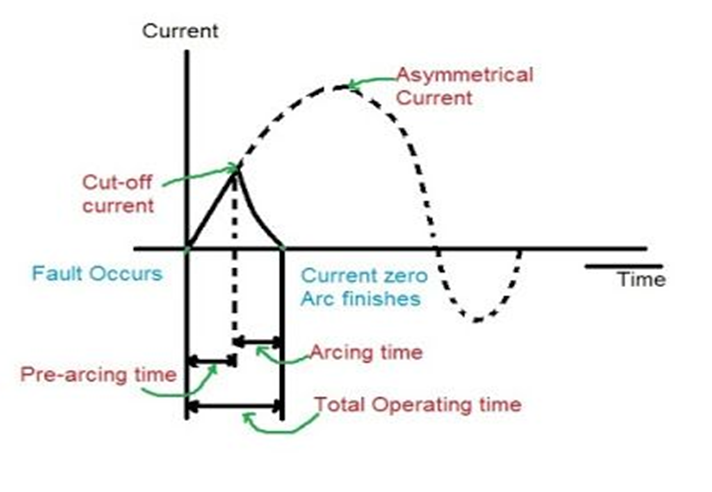
10. Define the terms: i) Cut off current ii)Pre-arcing time iii) Arcing time iv) Total operating time v)Breaking capacity ?
i) Cut off current: The maximum value of the fault current actually reached before the fuse melts is called cut off current.
ii)Pre-arcing time : This is the time between the commencement of the fault current and the instant that the arc is initiated.
When a fault occurs the fault current rises rapidly and generates heat in the fuse element. As the fault current reaches the cut off value, the fuse element melts and an arc is initiated. The time from the start of the fault current to the instant of the arc is initiated is known as pre-arcing time.it is generally small value.(0.001 second)
iii) Arcing time: This the time between the end of pre arcing time and the instant, when the circuit is open (arc is extinguished) & the current becomes permenantly zero.
iv)Total operating time: It is the sum of pre arcing time and arcing time.
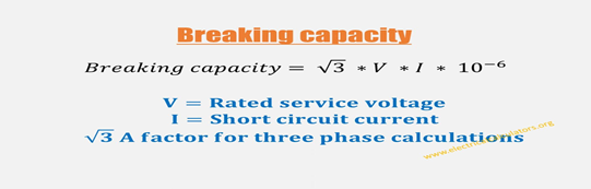
v)Breaking capacity : This is the rms value of ac component of maximum prospective current that a fuse can deal with at rated service voltage.
Notes:
Types of fuses
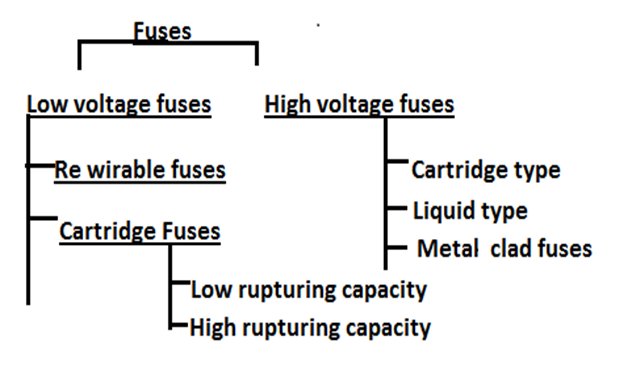
Semi closed rewirable fuse:
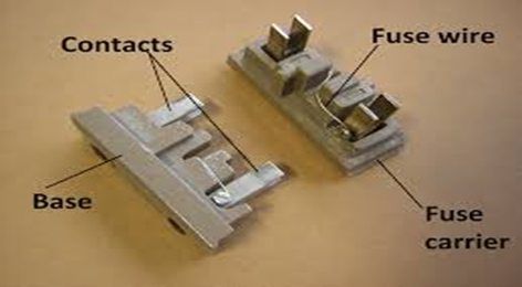
Semi closed type rewirable fuse also known as kit-kat type. Is used where low value of fault current are to be interrupted. It consists of a fuse base & fuse carrier. Fuse Base of made by porcelain and carries the fixed contacts to which the incoming and out going phase wires are connected. The fuse carrier also of porcelain and holds the fuse element(tinned copper/ alloy of tin & lead)
When a fault occurs, the fuse element is blown out and the circuit is interrupted. The fuse carrier is taken out and replace the fuse element & reinserted.
- Simple construction & low initial and renewal cost.
- Fuse elements are alloy of tin and lead, tinned copper wire….
Disadvantages :1) Deterioration of the fuse element by oxidation due to heating. ( due to oxidation through the continuous heating up of the element & reduction in cross sectional area leading increasing resistanca, ie. The current rating of the fuse element is decreased. The fuse operates at lower current than originally rated ie, premature rupturing.
- Low breaking capacity & lack of discrimination.
- Possibility of renewal by the fuse wire of wrong size or by improper material.
- Semi closed type fuses are made upto 500A.
- Used only for domestic and lighting loads.
Note : Rupturing capacity : It is the ability of a fuse to open the fault circuit without much arcing or damage itself.
11) With the neat sketch, Explain HRC Fuse Construction & Working?
Construction :
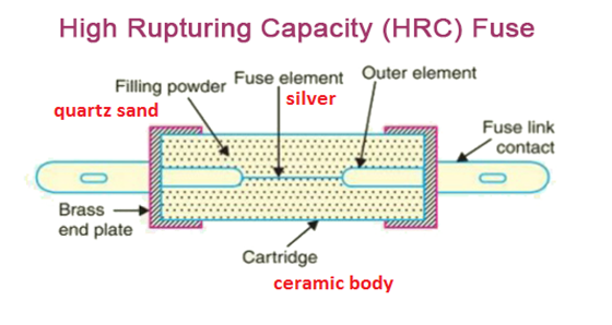
- It is the one of the simplest form of low voltage fuse & adopted for distribution purposes.
- They are cylindrical in shape, and are made of heat resisting Ceramic material.
- Fuse element are enclosed in a air tight vaccum chamber, deterioration does not take place. Normally silver alloy used as fuse element.
- They have metal end caps (Brass ): they are fixed element between which is attached the fuse element. (Brass: Alloy of copper & zinc, high tensile strength & high resistant to corrosion )
- Outer space of fuse element within the body is filled with filling powder or quartz sand or silica ….(for quench the arcing quickly without any hazards and act as a cooling medium)
Working :
- Under normal load condition: the fuse element is at a temperature below its melting point. Ie, it carries the normal current without over heating.
- Faulted condition : When a fault occurs ,the current increases and the fuse element melts before the fault current reaches its first peak. The heat produced in the process vaporizes the melted silver element.
- The chemical reaction between the silver vapour and the filling powder results in the formation of a high resistance substance forms like globules which helps in quenching the arc and cooling without making spark or gas.
12) Explain advantages & disadvantages of HRC Fuses?
Advantages:
- They are capable of clearing high as well as low fault current.
- They do not deteriorate with oxidation & age.
- They have high speed of operation.
- They have inverse current time characteristics.
- They require no maintenance, ie, they are cheaper than other circuit interrupting devices.
- No external flame, ie. safety of operation is very good.
- Fusing factor is 1.1
- They provide reliable discrimination.
Disadvantages:
- They have to be replaced after each operation.
- Heat produced by the arc may affect the associated switches.
- It produces over heating of adjascent switches.
13) Explain the criteria of selection of HRC Fuses?
- The normal current of the circuit.
- The extent which the over current protection is needed.
- The circuit voltage available across the fuse after its operation as it should not be more than the rated voltage of the fuse.
- The rupturing capacity of the fuse should not be less than the current to be broken.
- The extent of discrimination needed when it is used along with other fuses.
14) Define Circuit breaker?
A circuit breaker is a mechanical switching device, which can open or close a circuit under normal as well as fault condition. Which can,
1) make or break a circuit either manually or by remote control under normal conditions.
2) break a circuit automatically under fault condition.
3) make a circuit either manually or remote control under fault conditions.
15) With the neat sketch, Explain Circuit Breaker Construction & Working?
Construction
- Mainly it consists of a fixed contact and movable sliding contact, called electrodes following a relay circuit and tripping circuit
- Relay circuit for detects the faults and supplies information to the breaker for circuit interruption.It consists of a Current transformer :and a tripping circuit.
- Current transformer : primary winding of CT is connected in series with the circuit to be protected and secondary of CT connected the relay operating movable contact.
- Tripping coil : It contains a source of supply, trip coil of circuit breaker and relay stationary contacts.
Working:
Under Normal condition : The emf of the secondary winding of a Current transformer is small, and the current flowing in the relay operating coil is insufficient to close the relay contacts. This keep the trip coil of the circuit breaker unenergized. ie, the circuit breaker movable contacts is in closed position under normal conditions.
Faulted Condition: When a fault occurs, a large current flows through the primary winding of CT, This increase the secondary emf & hence the current through the relay operating coil. The relay contacts are closed and the trip coil of the breaker is energized to open the contacts of the circuit breaker.
16) Explain the different arc extinction methods adopted in a Circuit breaker?
There are two methods of extinguishing the arc in circuit breakers …
1.High Resistance Method
2.Low Resistance Method / Zero current method
High Resistance Method
- Application: Low voltage / Medium voltage of AC or DC Circuit breakers…(MCB)
- Resistance of the arc is increased rapidly to a high value with time so that current is reduced to a value, such that the voltage of source is no longer enough to maintain the arc voltage and arc is extinguished. The principle disadvantage of this method is enormous energy is dissipated in the arc. So it is used in low capacity DC and AC circuit breakers.
- The resistance of the arc may be increased by,
1)Lengthening the arc 2)Cooling the arc 3)Reducing the cross section of the arc 4)Splitting the arc
Low resistance / zero current method :
- In 50 Hz AC current wave form, natural current zero occurs after every 10msec. At current zero arc has no energy from source. In zero point interruption, plasma quickly removed from the contact space by various techniques.
- Only heat of arc has times constant which results in continuation of arc during next half cycle.
- The dielectric strength of the contact space is built very rapidly after current zero so that arc is extinguished. The rapid increase of dielectric strength of the medium near current zero can be achieved by, a) Causing the ionized particle in the space Between contacts to recombine into neutral molecules. b)sweeping the ionized particles away and replacing them by unionized particle.
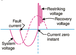
Define Re-striking Voltage?
Restriking voltage is the transient voltage appearing across the breaker contacts immediately after the opening of breaker contacts.
16)Explain the working of Oil circuit breaker?
Oil circuit breakers:
- Insulating oil like Transformer oil is used as arc quenching medium.
- Transformer oil has very good dielectric strength ie, 110kV/cm.
- In oil circuit breaker the contacts of the breaker are made to separate within an insulating oil.
Working Principle :
During the normal operating conditions, the contact of the oil circuit breaker is closed and carry the current. When the fault occurs in the system, the contacts of the breaker are moving apart under the insulating oil, and an arc is struck between the contacts.
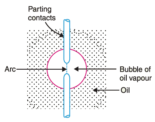
hydrogen at high pressure.The hydrogen gas occupies a volume of about one thousand times that of the oil decomposed. The oil is there fore, pushed away from the arc and expanding hydrogen gas bubble surrounds the arc and adjacent portions of the contacts. Hydrogen gas has high heat conductivity and cools the arc, thus aiding deionisation between the contacts , then gas set up turbulence in the oil and forces it into the space between contacts, thus eliminating the arcing product from the arc path. The result is that arc is extinguished and circuit current interrupted.
17) List the Advantages and Disadvantages of Oil circuit breaker?
Advantages:
- The oil has a high dielectric strength and provides insulation between the contact after the arc has been extinguished.
- The oil used in circuit breaker provides a small clearance between the conductors and the earth components.
- The hydrogen gas is formed in the tank which has a high diffusion rate and good cooling properties.
Disadvantages:
- The oil used in oil circuit breaker is inflammable and hence, cause a fire hazard.
- There is a risk of formation of explosive mixture with air.
- Due to decomposition of oil in the arc, the carbon particles is generated which polluted the oil and hence the dielectric strength of the oil decreases.
18)Explain the working of Air blast circuit breaker?
- High pressure air blast as an arc quenching medium.
- Also called compressed air circuit.
- ABCB used compressed air/ gas .as the arc interruption medium.
- Air blast cools the arc and sweeps away the arcing products to the atmosphere.
- Increase the dielectric strength of medium between contacts and prevents from re establishing the arc.so the arc extinguished immediately.
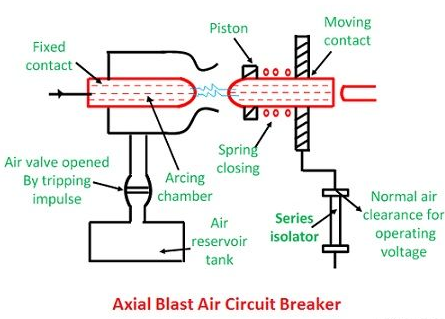
Construction:
- Fixed & Moving contacts : held in closed position by spring pressure under normal condition within the arcing chamber.
- Arcing Chamber is connected to the air reservoir tank with an air valve. This valve remains closed under normal operations, but opens automatically by tripping impulse occurs on the system.
- An additional compressed plant is connected to air reservoir for maintain sufficient capacity high pressure air production.
- Series isolator : Normal air clearance for working voltage
Working:
when any fault occures in the system, the tripping impulse causes the air valve which connects the breaker reservoir to the arcing chamber. The high pressure air entering the arcing chamber pushes the moving contact against the spring pressure. The moving contacts is seperated and an arc is struck. At the same time high pressure air blast flows along the arc and takes away the ionised particle along with it., so the arc is extinguished and current flow is interrupted.
Noted that , the contact separation required for interruption is gnerally small(1.75 cm)such a small gap may constitute inadequate clearance for the normal service voltage.so an series isolated switch is used for the normal air clearance for the operating voltage, it opens immediately after fault interruption .
19) List the Advantages Air blast circuit breaker?
- Risk fire is eliminated
- Faster operation
- Pollution less
- Less maintenance & simple assembly
- Contact gap is small so reduce the size of device
- Suitability for repeated operation
- Small arcing time-less burning of contacts
- Energy supplied for arc extinction is independent of the current to be interrupted
20)Explain the working of Vacuum circuit breaker?
- Vacuum used as an arc quenching medium. The operation of switching on and closing of current carrying contacts and interrelated arc interruption takes place in a vacuum chamber in the breaker which is called vacuum interrupter
- Vacuum offers the highest dielectric strength ie, 170 kV.
- When contacts of a breaker are opened in the vacuum, the interruption occurs at first current zero with dielectric strength between the contacts building up at a rate thousands of times higher than that obtained with other types of circuit breakers.
Construction:
- It consists of fixed contact, moving contact and arc shield mounted inside a vacuum chamber (vacuum interrupter). Metal end cap attached upper and lower part of the contacts
- The movable member is connected to the control mechanism by stainless steel bellows. This enables the permanent sealing of the vacuum chamber so as to eliminate the possibility of the leak.
- A glass vessel or ceramic vessel is used as the outer insulating body envelope for observation.
- The arc shield prevents the deterioration of the internal dielectric strength by preventing metallic vapors from falling on the inside surface of the outer insulating cover.
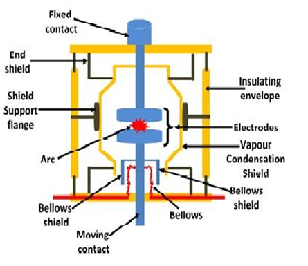
Working:
The pressure inside the vacuum interrupter is maintained below10^-4 torr.When the breaker operates, the moving contacts separates from the fixed contact and an arc is struck between the contacts. The production of arc is due to the ionization of metal ions depends very much upon the material of contacts. The arc is quickly extinguished because the metallic vapours, electrons and ions produced during arc are diffused in a short time and seized by the surfaces of moving and fixed members and shields. Since vacuum has very fast rate of recovery of dielectric strength, the arc extinction in vacuum breaker occurs with a short contact separation (0.625).
21) List the Advantages Vacuum circuit breaker?
- There are no fire hazards
- Pollution less, There is no generation of gas during and after operation.
- Little require little maintenance and are quiet in operation.
- Reliable and have longer life.
- Application ranging from 22kV to 66 Kv.
- Can be used for frequent switching.
- They can interrupt any fault current.
- They can successfully withstand lightning surges.
- Best interrupting low current applications such as shunt reactor switching, transformer switching, capacitor bank switching.
22)Explain the working of SF6 circuit breaker?
- sulphur hexafluoride (SF6) gas is used as the arc quenching medium.
- The SF6 is an electro-negative gas and has a strong tendency to absorb free electrons. The contacts of the breaker are opened in a high-pressure flow of SF6 gas and an arc is struck between them. The conducting free electrons in the arc are rapidly captured by the gas to form relatively immobile negative ions. This loss of conducting electrons in the arc quickly builds up enough insulation strength to extinguish the arc.
- It is colourless, odourless, non-toxic, and non-inflammable gas.
- SF6 gas is extremely stable and inert, and its density is five times that of air.
- It has high thermal conductivity better than that of air and assists in better cooling current carrying parts.
- It has a unique property of fast recombination after the source energising spark is removed. It is 100 times more effective as compared to arc quenching medium
Construction :
SF6 circuit breakers mainly consist of two parts, namely (a) the interrupter unit and (b) the gas system.
Interrupter Unit – This unit consists of moving and fixed contacts are enclosed in a chamber containing SF6 gas. When the contacts of the breaker are opened, the valve mechanism permits a high pressure SF6 gas from the reservoir to flow towards the arc interruption chamber. The fixed contact is a hollow cylindrical current carrying contacts fitted with an arc horn. The moving contact is also a hollow cylinder with rectangular holes in the sides to permit the SF6 gas to let out through these holes after flowing along and across the arc. The tips of fixed contact and moving contacts and arcing horn are coated with copper – tungsten arc resistance material.
Gas System – The closed circuit gas system is employed in SF6 circuit breakers. The SF6 gas is costly, so it is reclaimed after each operation. This unit consists low and high-pressure chambers with a low-pressure alarm along with warning switches. When the pressure of the gas is very low due to which the dielectric strength of gases decrease and an arc quenching ability of the breakers is endangered, then this system gives the warning alarm.
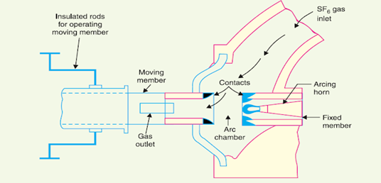
Working Principle of SF6 Circuit Breaker
In the normal operating conditions, the contacts of the breaker are closed. When the fault occurs in the system, the contacts are pulled apart, and an arc is struck between them. The displacement of the moving contacts is synchronised with the valve which enters the high-pressure SF6 gas in the arc interrupting chamber at a pressure of about 14kg/cm^2.
The high pressure SF6 gas absorbs the free electrons in the arc path and forms ions which do not act as a charge carrier. The result is that medium between the contact quickly increase the dielectric strength and causes the extinction of arc. After the breaker operation the valve is closed by the action of a set of springs, This process reduces the pressure of the SF6 gas up to 3kg/cm^2 thus; it is stored in the low-pressure reservoir. This low-pressure gas is pulled back to the high-pressure reservoir for re-use.
23) List the Advantages & Disadvantages of SF6 circuit breaker?
Advantages of SF6 Circuit Breaker:
- SF6 gas has excellent insulating, arc extinguishing and many other properties which are the greatest advantages of SF6 circuit breakers.
- The gas is non-inflammable and chemically stable. Their decomposition products are non-explosive and hence there is no risk of fire or explosion.
- Electric clearance is very much reduced because of the high dielectric strength of SF6.
- Its performance is not affected due to variations in atmospheric condition.
- It gives noiseless operation, and there is no over voltage problem because the arc is extinguished at natural current zero.
- There is no reduction in dielectric strength because no carbon particles are formed during arcing.
- It requires less maintenance and no costly compressed air system is required.
- SF6 performs various duties like clearing short-line faults, switching, opening unloaded transmission lines, and transformer reactor, etc. without any problem.
Disadvntages of SF6 Circuit Breaker:
- SF6 gas is suffocating to some extent. In the case of leakage in the breaker tank, the SF6 gas being heavier than air and hence SF6 are settled in the surroundings and lead to the suffocation of the operating personnel.
- The entrance of moisture in the SF6 breaker tank is very harmful to the breaker, and it causes several failures.
- The internal parts need cleaning during periodic maintenance under clean and dry environment.
- The special facility requires for transportation and maintenance of quality of gas.
24) Compare Fuse and circuit breaker?
| FUSE | CIRCUIT BREAKER |
| It provides both detection and interruption process. | Circuit breaker performs only interruption. Faults are detected by relay system. |
| Fuses can be used only once. | Circuit breakers can be used a number of times. |
| It does not give any indication. | It gives an indication of the status |
| No auxiliary contact is required. | They are available with auxiliary contact. |
| Fuse cannot be used as as an ON/OFF switch. | The Circuit breaker is used as an ON/OFF switches. |
| They are independent of ambient temperature | Circuit breaker Depends on ambient temperature |
| The Characteristic curve shifts because of the ageing effect. | The characteristic curve does not shift. |
| Breaking capacity of the fuse is low as compared to the circuit breaker. | Breaking capacity is high. |
| Operating time of fuse is very less (0.002 seconds) | Operating time is comparatively more than that of the fuse. (0.02 – 0.05 seconds) |
| Only single pole version is available. | Single and multiple version are available. |
| Completely automatically. | Manually as well as automatically operated. |
25) Define the terms
1)Breaking capacity 2)Making capacity 3)Short time rating 4)Norminal current rating ?
Breaking Capacity : It is the rms value of current which the circuit breaker capable of breaking at given recovery voltage and under specified conditions.
Making Current : The peak value of current during the first cycle of current wave after the closure of circuit breaker is known as making current.
- Making Current = 2.55 x symmetrical breaking capacity
Short time rating : It is the period for which the circuit breaker is able to carry fault current while remaining closed…
Normal Current rating: It is the rms value of current which the circuit breaker is capable of carrying continuously at its rated frequency under specified condition.
II Unit -PROTECTIVE RELAYS AND PROTECTION
- Define Pick up current of a relay ?
It is the minimum current in the relay coil at which the relay starts to operate. If the current through the Relay coil is less than the pick-up value then Relay won’t operate.
2. Explain the basic requirements of protective relays?
- Sensitivity: ability of the system to operate with low value of actuating current.
- Reliability: It is the ability of the Protective Relay system to operate under the pre-determined conditions. Without reliability, the protection would be rendered largely ineffective and could even become a liability.
- Simplicity: The relaying system should be simple so that it can be easily maintained. Reliability is closely related to simplicity.
- Economical: The most important factor in the choice of a particular protection scheme is the economic aspect.
- Selectivity: It is the ability of the system to select correctly that part of the system in trouble and disconnect the faulty part without disturbing the rest of the system.
- Speed: The relay system should disconnect the faulty section as fast as possible. The relay system should disconnect the faulty section as fast as possible for the following reasons,
- Electrical apparatus may be damaged if they are made to carry the fault currents for a long time.
- A failure on the system leads to a great reduction in the system voltage. If the faulty section is not disconnected quickly, then the low voltage created by the fault may shut down consumers motors and the generators on the system may become unstable.
- The high speed relay system decreases the possibility of development of one type of fault into the other more severe type.
3. Explain the classification of relay based on their constructional principle?
OR
Explain the working of attracted type relay with neat diagram?
Basic Relays
Most of the protective relays in service on electric power system today are of electro-mechanical type. They work on the following two main principles,
- Electromagnetic attraction
- Electromagnetic induction
Electromagnetic attraction:
Electromagnetic relays are those relay which operates on the principle of electromagnetic attraction. It is a type of a magnetic switch which uses the magnet for creating a magnetic field. The magnetic field then uses for opening and closing the switch and for performing the mechanical operation.their are mainly two types, Attracted armature type and solenoid type.
1. Attracted armature type relay:
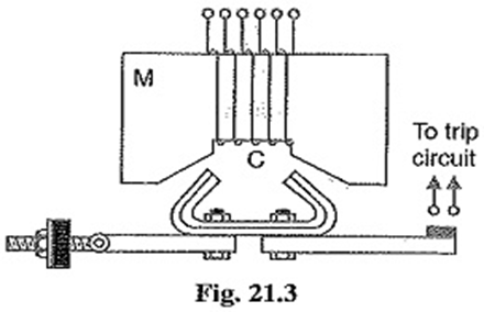
In this relay, the armature is attracted to the pole of a magnet. The electromagnetic force exerted on the moving element is proportional to the square of the current flow through the coil. This relay responds to both the alternating and direct current.
It consists of electro magnet M carrying a coil C and a pivoted laminated armature. The armature is balanced by a counter weight and carries a pair of spring contact fingers at its end. Normal operating conditions, the current through the relay coil C is such that counter weight holds the armature in the position shown in figure. When a short circuit occurs, the current through the relay coil increases sufficiently and the relay armature is attracted upwards. The contacts on the relay armature bridge a pair of stationary contacts attached to the relay frame. This completes the trip circuit which results in the opening of the circuit breaker and there fore in the disconnection of the faulty circuit.
- Solenoid type relay:
It consists of a solenoid and a movable iron plunger arranged as shown. Under normal operating conditions, the current through the relay coil C is such that it holds the plunger by gravity or spring in the position shown. However, on the occurrence of a fault, the current through relay coil becomes more than the pick up value, causing the plunger to be attracted to the solenoid. The upward movement of the plunger closes the trip circuit, thus opening the circuit breaker and disconnecting the circuit breaker and disconnecting the faulty circuit..
Electromagnetic Induction relay
- Most widely used for AC quantity
Electromagnetic-induction relays use the principle of the induction motor where torque is developed by induction in a rotor; this operating principle applies only to relays actuated by Alternating Current, and called Induction Type relays. Induction-type relays are the most widely used for protective-relaying purposes involving AC quantities.
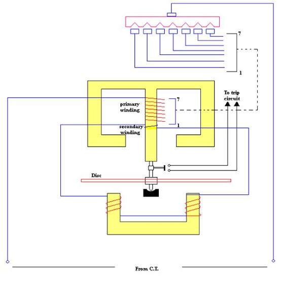
An Induction Type Relay essentially consists of a pivoted aluminium disc placed in two alternating magnetic fields of the same frequency but displaced in time and space. Actuating force is developed in a movable element that may be a disc or other form of rotor of non-magnetic current-conducting material by the interaction of electromagnetic fluxes with eddy currents that are induced in the rotor by these fluxes.
In Induction Relay Torque Equation, Two magnetic fluxes Φ1 and Φ2 differing in time phase penetrate through a disc. These alternating fluxes induce emfs e1 and e2 in the disc which lag their respective fluxes by 90°. These emfs lead to the flow of eddy currents i1 and i2. By the interaction of Φ1 with i2 and Φ2 with i1 a driving torque is produced.
4.Explain the working of induction type directional over current relay?
In order to make directional over current relay to operate to a fault flowing in a specified direction, directional element is added to non directional relay.Directional Overcurrent Relay which is designed to be almost independent of system voltage and power factor.
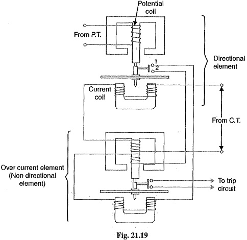
Constructional details: Fig. 21.19 shows the constructional details of a typical Induction Type Directional Over current Relay. It consists of two relay elements mounted on a common case viz.
- Directional element and
- Non-directional element.
1. Directional element: It is essentially a directional power relay which operates when power flows in a specific direction. The potential coil of this element is connected through a potential transformer (P.T.) to the system voltage. The current coil of the element is energised through a C.T. by the circuit current. This winding is carried over the upper magnet of the non-directional element. The trip contacts (1 and 2) of the directional element are connected in series with the secondary circuit of the over current element. Therefore, the latter element cannot start to operate until its secondary circuit is completed. In other words, the directional element must operate first (i.e. contacts I and 2 should close) in order to operate the overcurrent element.
2. Non-directional element: It is an over current element similar in all respects to a non-directional over current relay . The spindle of the disc of this element carries a moving contact which closes the fixed contacts (trip circuit contacts) after the operation of directional element.
Operation: Under normal operating conditions, power flows in the normal direction in the circuit protected by the relay. Therefore, Induction Type Directional Over current Relay (upper element) does not operate, thereby keeping the over current element (lower element) unenergised. However, when a short-circuit occurs, there is a tendency for the current or power to flow in the reverse direction. Should this happen, the disc of the upper element rotates to bridge the fixed contacts 1 and 2. This completes the circuit for over current element.The disc of this element rotates and the moving contact attached to it closes the trip circuit. This operates the circuit breaker which isolates the faulty section.
5. With neat sketch explain the construction & working of Buchholz Relay?
- The Buchholz relay is a safety device which protects the transformer from internal incipient faults(slow developing faults such as insulation failure of winding, core heating, fall of oil level due to leaky joints etc..).
- It is the gas actuated relay installed in oil immersed transformers for protection against all kinds of faults.
- This relay is used in the transformer having the rating higher than 750 KVA.
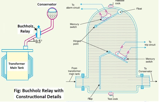
- Buchholz relay is placed between the main tank and the conservator.
Construction:
Buchholz relay is placed between the main tank and the conservator. Buchholz relay consists of an oil filled chamber. It consists of two element, the upper element, and the lower element.Where the upper element includes a mercury type switch linked to a float and The mercury switch on the upper float is connected to an alarm circuit during incipient faults Similarly, the lower element comprises of a mercury switch increased on a hinged kind flap situated on the straight line of oil flow and that on the lower float is connected to an external trip breaker in case of severe internal faults.
Working :
- In case of incipient (minor slow developing) faults within the transformer, the heat due to fault causes the decomposition of transformer oil in the main tank and bi product of decomposition contains more than 70 % of hydrogen gas and other gases. Hydrogen gas bubbles are light in weight tries to go into the conservator through buchholz relay. These gas bubbles flow in upward direction and get collected in the buchholz relay. The collected gas displaces the oil in buchholz relay and the displacement is equivalent to the volume of gas collected. The displacement of oil causes the upper float to close the upper mercury switch which is connected to an alarm circuit. Hence, when minor fault occurs, the connected alarm gets activated.
- If serious faults occurs in the transformer, an enormous amount of gas is generated in the main tank. the oil in the main tank rushes towards the conservator through the buchholz relay and in doing so tilts the flap to close the contact of mercury switch. This completes the trip circuit to open the circuit breaker controlling the transformer.
Advantages of Buchholz relay.
- Simplest form of transformer protection.
- It detects the incipient faults at a stage much earlier than as possible.
Disadvantages of Buchholz relay.
- The relay is used only in oil immersed transformer.
- It can only detect the fault below oil level.
- The response time of the relay is high.The minimum operating time of the relay is 0.1 seconds.
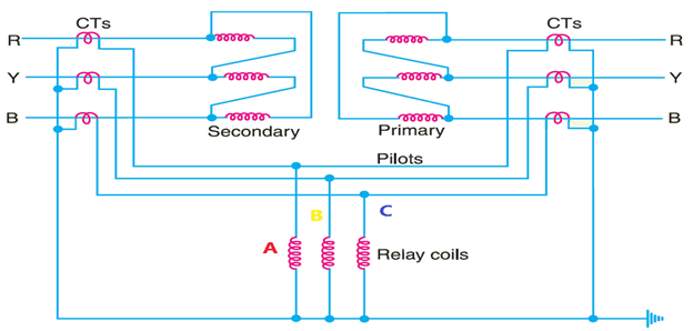
6. With neat sketch explain the construction & working of Differential Protection Method of Alternator?
Differential Protection of Alternators or Merz-Price circulating current protection
- Differential protection or Mertz Price circulating current is mainly employed for the alternator stator winding protection against earth faults and phase-to-phase faults by use of circulating current principle.
- It function on the concept of comparing the two currents in and out of stator coil. In normal condition the two current will be same, if fault occurs there will be some difference , The difference of the currents under fault conditions is arranged to pass through the operating coil of the relay. The relay then closes its contacts to isolate protected section from the system.
Arrangement for Differential Protection System
The protection system requires two identical transformers CT1 & CT2 which are mounted on both sides of the stator windings. So for three phase there are six no of CT’s. The secondaries of all CT’s are connected in star and other winding of each CT’s set are connected through cable called pilot cable. Three coil are connected in pilot cable. They are connected in a equipotential point of pilot cable. The equipotential point of the pilot wire is its centre, so the relay is located at the midpoint of pilot wires. The relay coils are connected in star. The neutral of the current transformer and the relay are connected to the common terminal. The relays are generally of electromagnetic type.

Working:
Under normal condition, the current at both ends of each winding will be equal and there will be no current difference in two sides of protected zone, hence Two ct’s in a phase will conduct same current. ie, there is a balanced circulating current in the piolet wires and no current flows through the operating coils(R1,R2,R3).
- Earth fault occurs on the R phase of the network because of the insulation breakdown to earth. current in that phase will flow through the core and frame of the machine to earth, the circuit being completed through the neutral earthing resistance. The current in the secondary of the transformer becomes unequal. The differential currents flow through corresponding relay coil. Thus, the relay becomes operative and gives the command to the circuit breaker for operation.
- Short circuit fault occurs between any two phases, say Y and B then short-circuit current flows through these phases. The fault unbalanced the current flows through CTs. The differential current flows through the relay operating coil and thus relay trips their contacts.
7.With neat sketch explain the construction & working of Merz-Price circulating current protection of Transformer?
Differential protection system or Merz-Price circulating current method
Differential protection of a 3 phase delta/delta transformer used for the protection against phase to earth and phase to phase fault. Note that CTs on the two sides of the transformer are connected in star. This compensates for the phase difference between the power transformer primary and secondary. The CTs on the two sides are connected by piolt wires and one relay is used for each pair of CTs. In a power transformer, currents in the primary and secondary are usually different; therefore, a differential current flows through the relay even under no fault conditions. This is compensated by different turn ratios of CTs. If T is the turn-ratio of power transformer, then turn ratio of CTs on the LV side is made T times that of the CTs on the HV side.
Working:
During normal operating conditions, the secondaries of CTs carry identical currents. Therefore, the currents entering and leaving the pilot wires at both ends are the same and no current flows through the relays. If a ground or phase-to-phase fault occurs, the currents in the secondaries of CTs will not be the same and the differential current flowing through the relay circuit will trip the breaker on both sides of the transformer. The-protected zone is limited to the region between CTs on the high-voltage side and the CTs on the low-voltage side of the power transformer.
8. Mention any two causes of insulation failure of a Relay?
- Over voltage due to switching
- Over voltage due to the direct and indirect lightning strokes.
- Bridging of conductors by birds.
- Mechanical damage of equipments.
- Break down of insulation due to decrease of its dielectric strength.
9. Explain the differential protection of a Bus Bar with neat diagram?
In differential protection method, currents entering and leaving the bus are totalized. During the normal working condition, the sum of these currents is equal to zero. When a fault occurs, the fault current upsets the balance and produces a differential current to operate a relay.
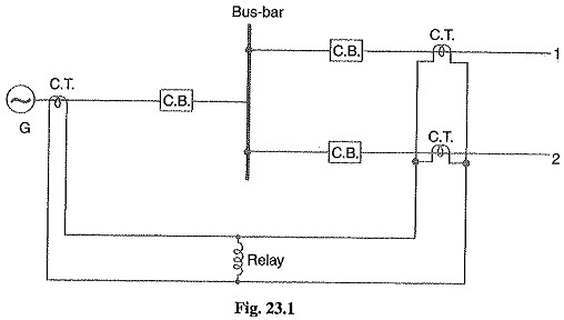
Fig.1 shows the single line diagram of current differential scheme for a station busbar. The busbar is fed by a generator and supplies load to two lines. The secondaries of current transformers in the generator lead, in line 1 and in line 2 are all connected in parallel. The protective relay is connected across this parallel connection. All CTs must be of the same ratio in the scheme regardless of the capacities of the various circuits.
Under normal load conditions or external fault conditions, the sum of the currents entering the bus is equal to those leaving it and no current flows through the relay. If a fault occurs within the protected zone, the currents entering the bus will not be equal to the current leaving the bus. The difference of these currents will flow through the relay and cause the opening of circuit breakers connected at the end of protected zone
10.Explain the Internal & External causes of Over voltage?
A sudden rise in voltage for a very short duration on the power system is known as voltage surge. The over voltage on a power system may be broadly divided into two main categories.
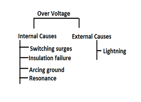
Internal Causes of Over voltage
- Switching Surges – The over voltages produced on the power system due to switching operations (opening and closing of a line using CB) are known as switching surges.
- Insulation failure – The most common case of insulation failure in a power system is the grounding of conductor (i.e. insulation failure between line and earth) which may cause over voltages in the system.
- Arcing ground – The phenomenon of intermittent arc taking place in line-to-ground fault of a 3φ system with an ungrounded neutral is known as arcing ground. The arcing ground produces severe oscillations (transients) of three to four times the normal voltage. The transients produced due to arcing ground may damage the equipment in the power system by causing breakdown of insulation. Arcing ground can be prevented by earthing the neutral.
- Resonance – Resonance occurs when inductive reactance of the circuit becomes equal to capacitive reactance. Under resonance, the impedance of the circuit is equal to resistance of the circuit and the p.f. becomes unity. Resonance causes high voltages in the electrical system.
External Causes of Overvoltage
- Lightning : An electric discharge between cloud and earth, between clouds, between the charge centres of the same cloud is known as lightning. Surges due to lightning are very severe and may increase the system voltage to several times the normal value.
11. Explain the protection scheme of Lightning surges?
Lightning surges may cause serious damage to the equipments in the power system, either by direct or by strokes on the transmission lines that reach the equipment as travelling wave. It is necessary to provide against both kinds of surges.The most commonly used devices for protection against lightning surges are :
1. Earthing screen : It consists of a network of copper conductors (generally called shield or screen) mounted all over the electrical equipment in the sub-station or power station. The shield is properly connected to earth on atleast two points through a low impedance. On the occurrence of direct stroke on the station, screen provides a low resistance path by which lightning surges are conducted to ground. In this way, station equipment is protected against direct strokes.
2. Overhead ground wires : The principle consists in creating one or more preferred impact points for a lightning strike using low impedance, conductor elements. These then conduct and dissipate the lightning current into the ground.The ground wires are placed over the transmission tower above the line conductors. When direct lightning strokes occur, ground wires will take up all the lightning strokes instead of allowing them to line conductors. The ground wires are grounded at each tower through a low resistance.In this way, station equipment is protected against direct strokes.
3.Lightning arresters (or surge diverters) : Lightning arrestor is connected between the line and earth. It is a protective device which conducts the high voltage surges (due to both direct and indirect stroke) on the power system to the ground and protects the equipments connected to it.
4.Surge absorber : A surge absorber is a protective device which reduces the steepness of wave front of a surge by absorbing surge energy. Although both surge diverter and surge absorber eliminate the surge, the manner in which it is done is different in the two devices. The surge diverter diverts the surge to earth but the surge absorber absorbs the surge energy.
12. Explain the Operation of Lightning Arrestor?
Lightning arrestor is connected between the line and earth. It is a protective device which conducts the high voltage surges (due to both direct and indirect stroke) on the power system to the ground and protects the equipments connected to it.
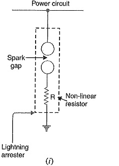
Basic operation of Lightning Arrestor
It consists of a spark gap in series with a non linear resistor. One end is connected to the protected terminal and other end connected to ground.The spark gap length is design to protect normal line voltage not enough to produce an arc. Non linear resistance,at normal frequency power system voltages the resistance is high and resistance decreases with the surge voltage increases.
- Under normal working: It is an off stage ie, it conducts no current to earth.
- Over volage condition : The air in the spark gap breaks down and an arc is formed, it provide a low resistance path for the surge to ground and protected the equipments.
- After the surge is over, the resistor offers high resistance to make the gap is non conducting.
13.Explain the Rod Gap Lightning Arrester with neat diagram?
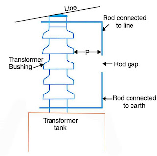
Figure shows the rod gap across the bushing of a transformer.
Construction: It consists of two 1·5 cm rods, which are bent at right angles with a gap in between. One rod is connected to the line and the other rod is connected to earth. The distance between gap and insulator (P) must be greater than one-third of the gap length so that the arc may not reach the insulator and damage it. The gap length is so adjusted that breakdown of air should occur at 80% of spark- over voltage in order to avoid cascading of very steep wave fronts across the insulators.
Working: Under normal operating conditions, the gap does not conducting. When a high voltage surge occur on the line, the air breaks and the surge current is conducted to earth. In this way, excess charge on the line due to the surge is conducted to earth without causing any damage to the insulator and equipments.
14. Explain the Horn Gap Arrester with neat diagram?
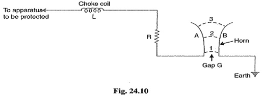
Construction: It consists of two horn shaped metal rods A and B separated by a small air gap. The distance between them gradually increases towards the top as shown. The gap between the horns is so adjusted that normal supply voltage is not enough to cause an arc across the gap. The horns are mounted on porcelain insulators. One end of horn is connected to the line through a resistance R and choke coil L while the other end is effectively grounded. The resistance R helps in limiting the follow current to a small value. The choke coil offers small reactance at normal power frequency but a very high reactance at transient frequency. Thus the choke does not allow the transients to enter the apparatus to be protected.
Working: Under normal conditions, the horn gap does not conduct (i.e. normal supply voltage is insufficient to initiate the arc between the gap). When an overvoltage occurs, spark-over takes place across the small gap G. The heated air around the arc and the magnetic effect of the arc cause the arc to travel up the gap. The arc moves progressively into positions 1, 2 and 3. At position 3, the distance may be too great for the voltage to maintain the arc. Consequently, the arc is extinguished. The excess charge on the line is thus conducted through the arrester to the ground.
15. Explain the Thyrite Type Lightning Arrester with neat diagram?
Thyrite is material obtained by mixing a special type of clay with carborundum (silicon carbide). Thyrite act as a nonlinear resistance. Resistance of Thyrite depends on voltage. It has high resistance at low voltage and low resistance at high voltage.
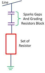
Construction : It consists of an spark gap in series with a set of thyrite disks. The spacing of the series gaps is such that it will withstand normal circuit voltage. Each disk is of 16 cm diameter and 1.75 cm thick. These disk are stacked one upon other. This arrangement is placed in a porcelain container. The non linear resistor discs are made of an inorganic compounds such as thyrite or Metrosil.
Working: Under normal working, the normal system voltage is insufficient to cause the break down of air gap assembly. When lightning occurs line voltage is raised to dangerously high voltage which results in the breakdown of electrode gap. Thus the high voltage reaches thyrite disks and resistance of thyrite reduces to a very low value. As a result the high voltage surge is discharged to earth. After the discharge thyrite comes back to its original condition without any permanent chemical change.
16. Mention about Soil Resistivity?
Soil resistivity is a measure of how much the soil resists or conducts electric current. Thus before designing and installing a new grounding system in an electrical substation, the location should be tested to find out the soil’s resistivity. The SI unit of resistivity is the Ohm-meter (Ω-m).
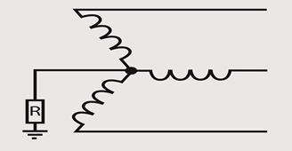
17.Different methods of Neutral grounding?
The process of connecting some electrical part of the power system (e.g. neutral point of a star connected system, one conductor of the secondary of a transformer etc.) to earth either directly or through some circuit element (e.g. resistance, reactance etc.) is called Neutral grounding.
18. Different methods of Neutral grounding?
Methods of Neutral Grounding
- Solid or effective grounding
- Resistance grounding
- Reactance grounding
- Peterson-coil grounding
- Voltage Transformer Earthing
19. Explain Solid grounding?
Solid grounding
Solid Grounding When the neutral point of a 3-phase system (e.g. 3-phase generator, 3-phase transformer etc.) is directly connected to earth (i.e. soil) through a wire of negligible resistance and reactance, it is called solid grounding or effective grounding.
20. Explain Advantages of Solid grounding?
Advantages of Neutral Grounding
- Voltages of the healthy phases do not exceed line to ground voltages i.e. they remain nearly constant.
- The high voltages due to arcing grounds are eliminated.
- The protective relays can be used to provide protection against earth faults. In case earth fault occurs on any line, the protective relay will operate the circuit breaker to isolate the faulty line.
- The overvoltages due to lightning are discharged to earth.
- It provides greater safety to personnel and equipment.
- It provides improved service reliability.
- Operating and maintenance expenditures are reduced.
III Unit –Lighting, Heating, Welding, & Electrolysis
- List the methods of Heat transfer?
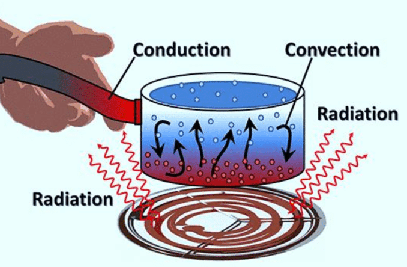
Heat from one body to another body can be transferred by following methods,
- Conduction
- Convection
- Radiation
2. List the materials used for Electric Heating?
- NICHROME : Alloy of Nickel & Chromium
- EUREKA / CONSTANTAN : Alloy of Nickel & Copper
- KANTHAL : Alloy of Iron, Chromium & Aluminium
3. Explain the Advantages of Electric Heating ?
- Cleanliness – Completely eliminate dust & ash
- No pollution – absence of flue gases
- Ease of control – manual or fully automatic control of heat is possible
- High temperature
- Uniform heating – conducting or non conductive material can be heated uniformly
- Localized heating is possible
- High efficiency – The over all efficiency of electric heating is high, since the heat can be produced directly in the charge itself.
- Low attention needed
- Less Floor area is required – electric furnace is more compact
- Better working conditions – no irritating noise
- Economical -electric furnaces are cheaper in their initial cost as well as maintenance cost, do not require big space for installation or for storage of coal and wood, no need to construct any chimney
- No carrying expense.
4. List the Requirements of Good heating Material?
- High Resistivity : This will reduce the length of the heating element.
- Low temperature coefficient of resistance : Lower the temperature coefficient of resistance of the material smaller the variation of resistance
- High melting point : It’s melting point should be sufficiently higher than its operating temperature otherwise, a small increase in temperature will destroy the element.
- Free from oxidation : The element material should not oxidise at high temperatures. Formation of oxidised layers will shorten its life.
- Non corrosive : The element should not corrode when exposed to atmosphere or any other chemical fumes.
- Ductile : It helps in obtaining different shapes and sizes of the element
- High mechanical strength : The element should possess high mechanical strength and should withstand vibrations.
- Economical : The cost of the material should not be high.
5.Explain the different Modes of Heat Transfer ?
The transmission of heat from one body to another because of the temperature gradient takes place by any of the following methods.
Conduction, Convection & Radiation
1. Conduction : In conduction, heat flows from object with higher temperature to object with lower temperature without the movement of molecules. In solid, heat is passed on to next neighboring molecules without shifting any transfer of molecules. Conduction is more predominant in solids.
Eg : Ironing of clothes is an example of conduction where the heat is conducted from the iron to clothes.
2.Convection : In convection heat transfer takes place from higher temperature regions to lower temperature regions due to actual motion of molecules. Prominent in liquids.
Example : Boiling of water – molecules that are denser move at the bottom while the molecules which are less dense move upwards resulting in circular motion of the molecules so that water gets heated.
3.Radiation : Radiation is a method of heat transfer that does not require a medium between the heat source and the heated object. Radiation is a form of energy transport consisting of electromagnetic waves traveling at the speed of light. Movement of charged electrons and protons is responsible for the emission of electromagnetic radiation. These electromagnetic waves carry away the energy from the emitting body and when they incide on another body the energy gets released to that object.
6. Explain the types of Resistance Heating?
When current passes through a resistance, power loss takes place and it appears in the form of heat. All the electrical energy given to a resistance heating element will be converted into heat energy .
The resistance heating is further classified as
Direct resistance heating , Indirect resistance heating , Infrared or Radiant heating
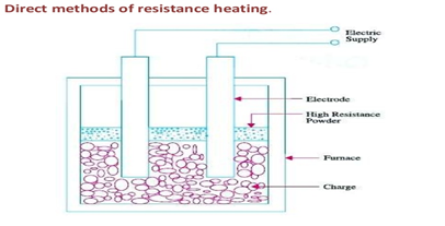
1: Direct resistance heating : In this method of heating, current is passed through the material or charge to be heated. The charge is taken in a furnace and two electrodes (or three electrodes for 3-phase) are immersed in the charge. The supply a c or d.c. will be given to the electrodes as shown in figure. The charge may be in the form of solid/metal pieces, powder or liquid. When solid/metal pieces are to be heated a powder of high resistivity material is sprinkled over the surface of the charge to avoid direct short-circuit. The resistance offered by the charge to the flow of current causes power loss I2R and it results in the heating of the charge.
This method provides high and uniform temperatures. This method has quiet high efficiency since heat is produced in the charge itself.
Application : Resistance welding , Electrode boiler for heating water
2. Indirect resistance heating : In this method the current is passed through a high resistance wire known as heating element as shown in figure. The heating element is placed inside a chamber so that there is no direct contact between the charge and heating element. Usually charge will enclose the heating element for efficient heat transfer. The heat produced in the element is transferred to the charge by radiation or convection methods.
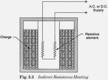
This method provides uniform temperature. Automatic temperature control can be provided in this method.
Application: room heaters , immersion water heaters , various types of resistance ovens used in domestic cooking.
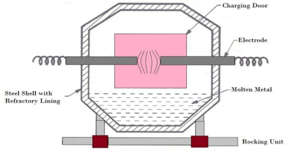
6. Explain Direct and Indirect Arc Furnace with neat diagram?
It is a method of electric heating in which charge is heated with the help of heat produced from ARC.
ARC : When the electric supply is given to two electrodes separated in air, air gap is subjected to very high voltage the air gets ionized due to electrostatic forces. The ionized air act as a conducting material, therefore the c starts flowing through the air gap in the form of continuous spark. ie, ARC.
There are two types of electric arc furnaces,
- Direct arc furnace
- Indirect arc furnace.
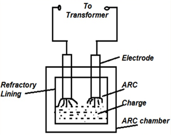
Direct Arc Furnace :
It consists of two electrodes. When supply is given to the electrodes, two arcs are established and current passes through the charge. The arc is in direct contact with the charge. Heat is developed due to arcs and a small amount of heat is also developed due to the electrical resistance of the charge. Therefore large amount of heat can be generated. For large capacity furnaces, 3-phase supply is used. The most important feature of the direct arc furnace is that, the current passing through the charge develops electromagnetic forces and necessary stirring action is automatically obtained by it. This result in uniform heating of the charge.
Application – Refining and melting of Steel.
Indirect arc furnace:
- In this type of furnace the arc exists between two electrodes and there is no direct contact between arc and charge. Made up of steel with refractory lining inside
- Arc is formed above the charge. heat developed in the charge is purely by the radiation from the arc.
- The temperature of the charge is lower than that in the direct arc furnace. As current does not flow through the charge, there is no stirring action.
- The furnace must be rocked mechanically. An electric motor is used to operate suitable grinders and rollers to provide rocking action to the furnace. Rocking action helps in thorough mixing and uniform heating of the charge. Hence, these furnaces are also known as rocking arc furnaces.
- Only used in single phase & Economical
Application – Melting of non-ferrous metals (does not contain iron, eg: Al,Cu,Zn)
7. Explain Direct Core type Induction Furnace with neat diagram?
Direct Core type induction furnace:
The core type of furnace is essentially a transformer in which the charge forms the secondary circuit. Charge is placed in the annular hearth which forms the single turn secondary circuit of the transformer. The charge is magnetically coupled to the primary by an iron core as shown in figure. To start the furnace, molten metal is poured in the annular hearth, otherwise the secondary winding is incomplete (open) and no current will flow through the charge and no heating will take place. In this type furnace an iron ring is placed at the bottom of the hearth.
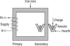
It can be seen from the diagram that the magnetic coupling between primary and secondary is very poor, resulting in high leakage current and a low power factor. Also the electromagnetic forces cause severe turbulence and stirring action if operated at normal frequency. Due to above two reasons, the furnace is operated at low frequencies of the order of 10 Hz. An additional motor generator set or frequency converter is needed to obtain this low frequency.
Disadvantages:
- A crucible of inconvenient shape is required.
- High leakage current & Low power factor due to poor magnetic coupling. To compensate this Furnace is operated at low frequencies of the order of 10 Hz.
- A Motor Generator set or frequency converter is required
- Some molten metal is necessary in the crucible to start the furnace
- It is bulky due to the presence of core
8 . Explain with neat diagram Coreless Induction Furnace?
The eddy currents developed in any magnetic circuit are given by the equation
eddy currents α B2 f2
B = maximum flux density (T)
f = frequency (Hz).
In coreless furnace, there is no core and thus flux density will be low.Compensating the low flux density, the primary current applied to the primary coil should have sufficiently high frequency(500-1000Hz).
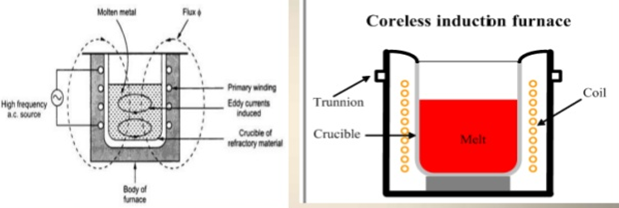
- It consists of a coil, it is wound around the crucible. This coil acts as primary of a transformer.
- Charge to be melted acts as the secondary of the transformer. Charge is placed in cylindrical in shaped ceramic crucible (Refractory).
- When supply is given to primary coil, it produces eddy-currents in the charge or crucible by transformer action. These currents heat the charge to melting point and they also set up electromagnetic forces which produce a stirring action in the charge.
- Due to high frequency of the supply, the skin effect in the primary coil increases the effective resistance of the coil and the copper loss. To reduce copper losses, hollow copper conductors are used in which cold water is circulated.
Application– melting of steel and other ferrous metals
Advantages
- High speed of heating.
- Low erection and operating costs.
- The automatic stirring action produced by eddy currents.
- Well suited for intermittent operations
- Their charging and pouring is simple.
- Precise temperature control.
- They can be used for all industrial applications requiring heating and melting.
- Most suitable for the production of high-grade alloy steels.
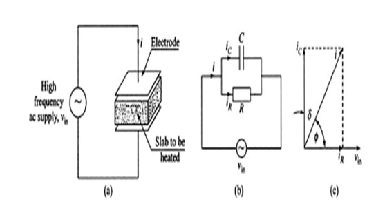
9. Explain with neat diagram Dielectric heating ?
When an insulating material is subjected to an alternating electric field, the atoms get stressed and due to the inter-atomic friction caused by repeated deformation and rotation of atomic structure (polarization) heat is produced. This loss is known as dielectric loss.Dielectric loss increases with increase in frequency and strength of the electric field. If the applied voltage (electric field applied) is very strong, it may results in rupture of the dielectric medium,Therefore, in dielectric heating high voltage is not used, instead high frequencies are used.
All dielectric materials can be represented by a parallel combination of a leakage resistor R and a capacitor C as shown in Fig. The total current I is made up of two components, IR and IC. The capacitive current IC leads V by 90° and leakage current IR is in phase with applied voltage and represents dielectric loss.
10.Write the Application of Dielectric heating ?
- Gluing and bonding of woods.
- Diathermy – treatment of certain body pains and diseases
- Preparation of thermo plastic resins
- Drying tobacco, paper, wood and rayon
- Welding of PVC
- Stress annealing textile fibres.
- Heating of bones and tissues.
- Sterilization of cereals and medical equipment
- Processing of rubber synthetic materials and chemicals during manufacture
- Heat-sealing of plastic sheets.
- Sewing of rain coats, umbrellas made of plastic film material
11.Write the Advantages & Disadvantage of Electric Welding ?
Advantages of Welding:
- A welded joint is as strong as the base metal.
- Welding equipment is not costly and is portable.
- Welding permits considerable freedom in design
- Welding permits considerable freedom in design.
- Welding products are lighter and strong.
- Welding joint are easier to inspect.
- A large number of similar and dissimilar metals and alloys can be welded
Disadvantages:
- Welding process requires skilled operators.
- Welding process gives harmful radiation and fumes.
- Welding requires edge preparation.
- Welding requires edge preparation.
12. Explain the principle of Spot, Seam & Butt Welding ?
In Resistance welding, heat required for the purpose of weld is produced by the resistance offered to the flow of current at the junction of two metals ie, I2Rt Loss. Resistance welding can be mainly classified into,
- Spot welding
- Seam welding
- Butt welding
Spot Welding:
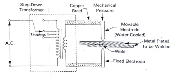
- It is usually employed for joining sheet metal structure.
- It Only provides mechanical strength and is not air or water tight.
- The workplace or plates to be welded are held between two electrodes and pressed together by mechanical pressure exerted through electrodes.
- The current is passed for a definite period of time, dependent upon the size of the plates. The heat produced between the workplace produce a spot weld.
- The unwanted heat generation between electrodes and work places is to be avoided either by water cooled electrodes.
- The welding current depends on the thickness and composition of the work pieces. It varies from1,000 to 10.000 ampere at low voltage of the order 1 to 15 volt.
Seam welding :
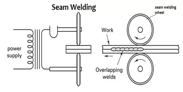
- Seam weld is a series of continuous spot welds.
- In this welding tipped electrodes are replaced by roller electrodes leads the contact area of electrode should be small. This will localize the current & pressure to the welding point.
- The two plates to be welded are passed in between roller electrodes.As these rollers travel over the metal pieces which are under pressure the current passing between them heats the two metal pieces to the plastic state and results into continuous spot welds.
- An interrupter used the turn on the supply for a period sufficient to heat the welding point. After the weld, joint is pushed ahead and at the time current is interrupted. Weld joint is cooled by splashing water over it.
- Depending upon the number of welding current pulses per second we get series of weld spots.
Butt welding:
It is two types, Upset butt welding & Flash butt weldinG
Upset butt welding :
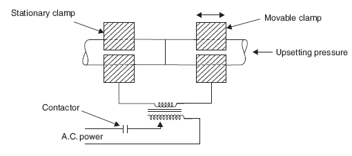
- Two work pieces to be welded together are fixed in clamps and butted against each other.
- Electrodes used are jaw type and these should be in a position to introduce high current without treating any hot spot on the job.
- When supply is switched-on, heavy current passes through the joint and heat is generated by the contact resistance between two work places. When efficient heat is developed, the work pieces are joined by axial force by a spring and produce a butt joint.
Flash butt welding:
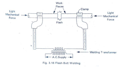
- It is little different from upset butt welding. In this process, the ends of
two work piece to be welded are put together under light axial mechanical pressure. A small gap will be remained in between the two work pieces before supply is given. When supply is switched on arcing will takes place. Arcing is allowed till the two ends of the work pieces reach welding/melting temperature, after that the supply will be switched off and the pieces are rapidly brought together with light pressure. As the pieces are moved together, the fused metal and slag come out of the joint making a good solid joint. The thin fin around the joint is removed to produce a sound weld.
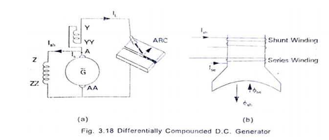
13.Explain about Welding Generator?
A differentially compounded D.C generator is used as welding generator. In this generator series field and shunt field windings are wound in opposite directions so that their fluxes oppose each other. The net field flux and the generated voltage are reduced as load current increases. Thus the generator has drooping V- I characteristics. Drooping means that the terminal voltage of welding machine decreases as the welding current increases. Reverse happens when load current decreases.
14. Explain the principles of Electrolysis?
- Process of chemical change taking place in a electrolyte by the passage of electricity is called Electrolysis
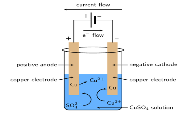
- It is a process of decomposition of an electrolyte substance, which is present in liquid state, when current is passed through it. The process of electrolysis takes place in cell known as electrolytic cell.
- It consists of a container, that contains an electrolytic solution ie, dilute solution of copper sulphate CuSO4. The electrolyte dissociated into copper and sulphate ions.The cell contains conducting plate called electrode. Copper plates are taken as electrode. Electrode connected to the positive terminal of the supply is called Anode. Electrode connected to the negative terminal of the supply is called cathode. Electrodes are connected to a source of power supply(DC).
- Due to applied potential across electrodes an electric field set up in the electrolyte and it exerts electric forces on the ions and cause them to move. The positively charged ions CU++ are attracted towards negative charged electrode that is cathode and SO4 moves towards anode. The current through the electrolyte is carried by these two moving streams of ions.
- When ions arrive at the electrodes, due to the energy of the battery, their charges are neutralized and ions become atoms. Thus when CU++ move to cathode, they leave their charge and become Cu atoms which are deposited over the cathode. Similarly SO4 moves towards anode and give up the charge there. If the anode is of copper then sulphate will react with it to form CuSO4.
- The whole process describe above is called Electrolysis.
15.State Fraday’s laws of Elctrolysis?
Faraday’s two laws stated as follows:
First law : The amount of material deposited or liberated over an electrode in an electrolytic cell is propotional to the quantity of electricity which has passed through it.
i.e. mass of chemical deposition,
m α Q , m α It , m = Zit
where Z is a constant depending upon the substance.
Second law : The amounts of chemical changes produced by the same quantity of electricity in different substances are proportional to their equivalent weights.
The equivalent weight = Atomic weight / Valency = a/v
Where, a = atomic weight & v = valency
16.Explain the field of Application of Electrolysis?
- Electroplating: It is a process of coating a thin film of a metal over a base metal by the passage of current in the electrolyte and for the protection of base metal from corrosion.In this method pure metal is to be used in coating, as anode and base metal take as cathode along with a suitable electrolyte. Eg: Gold coated over a copper plate.
- Extraction of metals: In this process. The ores are subjected to electrolysis to extract metals. Eg: Aluminium Extraction from Bauxite ore
- Purification of metals: Metals can be purified by electrolysis. In the purification of metals, the impure metal is used as anode and the pure metal plate is used as a cathode. When electricity is passed, the impure metal gets dissolved and pure metal gets deposited on the cathode.
- Electrotyping: It is used in preparing blocks used in printing.
- Production of chemicals: Various chemicals are produced with the help of electrolysis. Caustic soda, chlorine….
- Galvanization: It is the Process of coating a metal usually iron/steel, with a protective covering of zinc.
- Anodizing: Anodizing protects aluminum with a durable, attractive finish. In this process to coat aluminium or magnesium with a thin layer of oxide to help prevent corrosion.
17.Explain the Flood lighting?
It is employed for flooding any open large surface with light. high-intensity of filament lamps & discharge lamps are employed for the purpose. It is seud for advertisement, enhance the beauty of moument, sports stadium illumination, railway, quarries…
IV – Electric Traction
- What is Traction?
The process of moving any vehicle either in streets or in railway systems is called Traction. The system of traction involving the use of electricity is called electric traction. Electric traction is meant locomotion in which the driving force is obtained from electric motors.
2. Define Electric Drives?
An electric drive can be defined as an Electro-mechanical device for converting Electrical energy to mechanical energy to impart motion to different machines and mechanism for various kinds of process control. It is the combination of prime mover, controlling device, transmission equipment and mechanical working load, electric motor used as a prime mover.
*3. Draw the block diagram of Electric drive and explain?
Drives that employ electric motors as prime movers are known as electric drives. . It is the combination of prime mover, controlling device, transmission equipment and mechanical working load, electric motor used as a prime mover.
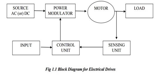
It basically consists of the following components,
- Source : A source can be anything AC or DC used in the system. 1 -Φ or 3 Φ, 50 Hz Ac is mostly used in the drive system in most locations.
- Power modulator: The main function of power modulator is to modulate the flow of power from a source to the motor. It modulates the power as per torque-speed characteristics required by the load. It regulates source and motor currents within some required value. It regulates the current in starting, braking and some speed reversal conditions.
- Electric motor: Motor is generally used in the system to convert electrical of energy into electrical energy. Motors used in electric drives are induction motors. Synchronous motors, Dc motors, stepper motors and also reluctance motors.
- Mechanical load: Load can be anything which consumes power. It is machinery, such as fans, blowers, pumps, robots and machines which performs a given task.
- Sensing unit: This unit is consists of current sensor or speed sensor. It senses the output speed or required quantity. Speed is sensed in the system by tachometer which is coupled with the motor. Current sensing is required in the system for current limit control. Sensing unit is directly attached to the controlling unit.
- Control unit: Sensed Output is given to the controlling unit. In controlling unit, Sensed output and required output is compared and some input command given to the controller for getting the required output. Various types of controllers are used in electric drives. Control unit controls the function of power modulator.
- Power transmission ( coupling/gear box /Chain /belt..)
4. Explain the Advantages & Disadvantages of Electric Drives?
- They have a longer life span than other drives systems.
- They are pollution free & clean due to absence of fuel, fumes etc.
- It is more economical.
- Electrical energy is transmitted easily.
- The noise level of electric drive is less.
- No need of any fuel storage and transportation.
- It has High efficiency.
- Regenerative braking is possible only in electric drives.
- Various speed control methods available.
- They require less space.
- It is reliable and economical source of power.
- It can be remotely controlled.
- Available in wide range of various parameters like speed, torque, and power.
- Electrical energy can be transported to long distances by transmission lines.
Disadvantages:
- It cannot be installed where electricity is not available. For installation of electric motor electrical energy is necessary.
- On the failure of electrical supply, the electrical drive system cannot work.
- It can cause noise pollution.
- The initial cost of the system is high.
5. List the factors governing selection of motor for an Electric Drives ?
- Nature of supply: AC Supply / Pure DC Supply /Rectified DC
- Electrical characteristics : Starting characteristics, Running characteristics, Speed control, Braking characteristics
- Mechanical characteristics : Nature of load, Noise level, Cooling system, Types of bearing, Methods of power transmission, Types of enclosure.
- Nature of drive: Individual , Group drive
- Size and rating of motors : Whether the motor is to drive continuous, intermittent, or variable load cycle.Whether its over load capacity and pull out torque are adequate.
- Cost : Capital cost & Running cost.
6. Explain the classification of Electric Drives ?
- Group drive:- When several machines are run on one shaft and the shaft is driven by a single motor is called group drive.
- Individual drive:- If one motor is used to drive one load.
- Multi motor Drive:- Separate motors are used for operating different parts of the same mechanism
7. Explain the working of Group Drives ?
When one prime mover or motor is used for the number of machine tools on common shaft then the drive is called as group drive . it is also sometimes called as shaft drive. The Group Drive system uses a high powered motor which drives an overhead shaft called the main shaft by means of chain or belt. The main shaft runs across the workshop from one end to other ends. The main shaft drives another shaft called counter shaft. Finally, the counter shaft drives the group of machines through belting and pulleys.
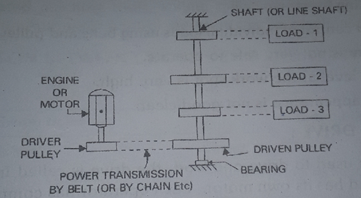
8. Explain Advantages & Disadvantages of Group Drives ?
Advantages :
- Cost of group drive is less for given capacity of load. cost of one motors of given capacity is less than the cost of many motors of the same capacity.
- Group drive has high overload capacity.
- Only one motor is to be handled.
- By proper load adjustment, it is possible to operate the motor at almost full load.
- The rating of the motor can be less than the sum of all loads used.
Disadvantages:
- The breakdown of main motor causes stoppage of all the operations. Considerable power loss takes place in the energy transmitting system.
- It is used in the process where stoppage of one operation requires the stoppage of sequence of operations as in case of textile mills.
- Speed control of individual machine is very difficult.
- Flexibility of layout of the various machines is lost in group drive since machines have to be installed to suit the layout of the line shafting.
- Extension of the process by installing new machine is limited.
- Group drives are less safe to operate.
- The noise level at the work spot is very high.
- If only small load is to be used, the motors has to work with light loads . his results in reduced efficiency.
- It does not give good appearances due to use of line shafting pulleys and belts.
- The drive appearance is not clean.
9. List any 7 Advantages & Disadvantages of Individual Drives ?
Advantages :
- A fault in the motor will not idle the other loads.
- The motor almost run always with full load, so high efficiency.
- It eliminates all shafting and belting.
- Machines can be installed at any desired place.
- Addition of future loads is easy.
- The speed control of individual load is easy.
- The system is very safe.
- The noise level is less.
- The appearance is good.
- Motors operate at good power factor.
Disadvantages:
- The fixed or initial cost is high.
- It is not suited for a sequence of operations.
- The over load capacity of each motor will be less.
10. List comparison between Individual Drives and group drives ?
| Individual Drive | Group Drive | |
| Initial Cost | High | Less |
| Flexibility | More Flexibility | Less Flexibility |
| Safety | It is more safe | It is less Safe |
| Reliability | It has high reliability | It has less reliability |
| Space required | More | Less |
| Overload Capacity | Less | Higher |
| Maintenance cost | More | Less |
| Speed control | Easily possible | Difficult |
| Mechanical Power transmission losses | Less losses | More Losses |
| Addition/Alternation | Easily possible | Easily not possible |
| Total HP | More | Less |
| Appearance | Good | Not good |
| Any one application of each | Lathe Machine | Textile Industry |
| Number of motors equal to number of machines. | Single large motor is used. |
*11. With neat figure explain the Speed time curve of Main line service?
Sketch the Speed time curve of Electric Traction system & Explain the different regions?
A speed time-curve is a graph showing the variation of speed with respect to time. The curve drawn between speed and time, taking speed on the Y axis and time on X-axis, is known as speed-time curve. The speed-time curve provides complete information of the motion of the train.
The distance between two stops in main line service is considerably more (usually more than 10 km). In this service free run is of longer duration. The duration of acceleration and retardation is a small fraction of total running time.
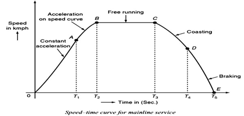
Speed-time curve mainly consists of,
1. Constant Acceleration or Acceleration during Notching Up or Rheostatic acceleration: During notching up period (0 to A) the current is maintained approximately constant and the voltage across the motor is gradually increased by cutting out the starting resistance. Thus tractive effort is constant and, therefore, acceleration remains constant during this period.
2. Speed Curve Running or Acceleration on Speed Curve: During speed curve running (A to B) the voltage acting across the motor remains constant and current starts decreasing with the increase in speed according to the characteristics of the motor and finally the current taken by the motor becomes constant. During this period, though the train accelerates but acceleration decreases with the increase in speed and finally becomes zero at the speed at which the tractive effort developed by the motor becomes exactly equal to the resistance to motion of the train.
3.Free Run or Constant Speed Run(B to C): At the end of speed curve running i.e., at B the train attains the maximum speed. During this period the train runs with constant speed attained at and constant power is drawn.
4. Coasting(C to D): At the end of free running period (i.e., at C) power supply is cut off and the train is allowed to run under its own momentum. The speed of train starts decreasing on account of resistance to the motion of train. The rate of decrease of speed during coasting period is known as coasting retardation.
5.Retardation or Braking Period(D to E): At the end of coasting period (i.e., at D) the brakes are applied to bring the train to rest. During this period speed decreases rapidly and finally reduces to zero.
12. With neat figure explain the Speed time curve of Urban & Sub urban service?
Urban Service: In urban or city service the distance between the two stops is comparatively very short (say 1 km or so). The time required for this run is very small (few minutes). The acceleration as well as retardation is required to be high so that high average speed and short time of run is obtained.
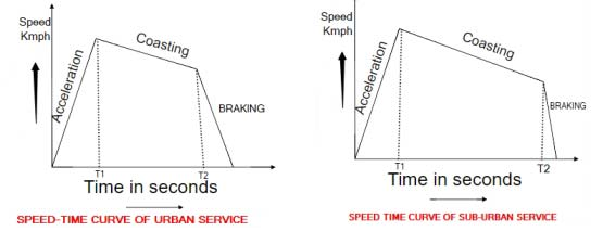
Suburban Service: In this service the distance between the stops is little longer than urban service but smaller than main line service (say between 2 and 5 km). Free run is still not possible. Coasting is for a comparatively longer period. Acceleration and retardation required are as high as for urban service.
13. Define Average speed & Scheduled speed of an Electric Train?
Average Speed: The mean of the speeds from start to stop i.e., the distance covered between two stops divided by the actual time of run is known as average speed.
Average speed = Distance between stops/Actual time of run, T
Schedule Speed: The ratio of distance covered between two stops and total time of run including time of stop is known as schedule speed.
Schedule speed = Distance between stops/ (Actual time of run + stop time)
schedule speed is always smaller than the average speed. The difference is large in case of urban and suburban services and is negligibly small in case of main line service.
14. List the Factors Affecting Scheduled speed of an Electric Train?
- Acceleration and braking retardation.
- Maximum or crest speed.
- Duration of stop.
1. Effect of Acceleration and Braking Retardation: For a given run and with fixed crest speed the increase in acceleration will result in decrease in actual time of run and, therefore, increase in schedule speed.
2. Effect of Maximum Speed: For a constant distance run and with fixed acceleration and retardation the actual time of run will decrease, and therefore, schedule speed will increase with the increase in crest speed. The effect of variation in crest speed on schedule speed is considerable in case of long distance run.
3. Effect of Duration of Stop: For a given average speed the schedule speed will increase by reducing the duration of stop. The variation in duration of stop will affect the schedule speed more in case of shorter distance run as compared to longer distance run.
15. Explain & Derive the Trapezoidal speed time curve?
Trapezoidal speed–time curve is close approximation of main line service where the duration of free running time is long.
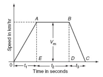
Let, D = distance between the stops in km, T = actual running time of train in second, α = acceleration in km/h/sec, β = retardation in km/h/sec, Vm = maximum or the crest speed of train in km/h, and Va= average speed of train in km/h.
Area under the trapezoidal speed–time curve gives the total distance between the two stops (D). ∴ The distance between the stops (D) = area of Trapezium OABCO
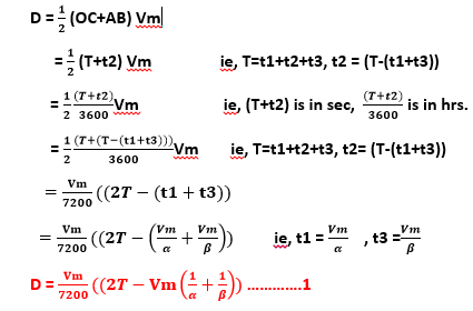
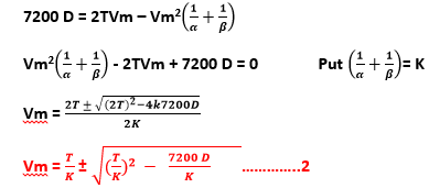
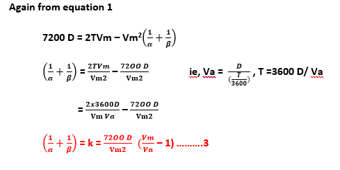
Quadrilateral Speed Time Curve of Urban & Sub urban Service
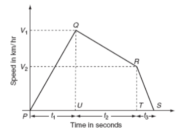
16. Define the Tractive effort?
It is the effective force acting on the wheel of locomotive, necessary to propel the train is known as ‘tractive effort’, Ft. The tractive effort is a vector quantity always acting tangential to the wheel of a locomotive. It is measured in newton. The net effective force or the total tractive effort (Ft) on the wheel of a locomotive or a train to run on the track is equals to the sum of tractive effort:
- Required for linear and angular acceleration (Fa).
- To overcome the effect of gravity (Fg).
- To overcome the frictional resistance to the motion of the train (Fr).
Ft = (Fa)+ (Fg)+ (Fr)
*17. Explain the term Specific Energy Consumption?
This quantity of energy consumed by the various parts of train per ton per kilometer is known as specific energy consumption. It is expressed in watt hours per ton per km.
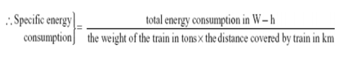
*18. Explain the Factors affecting the Specific Energy Consumption?
- Distance between stations : From equation specific energy consumption is inversely proportional to the distance between stations. Greater the distance between stops is, the lesser will be the specific energy consumption.
- Acceleration and retardation : For a given schedule speed, the specific energy consumption will accordingly be less for more acceleration and retardation.
- Maximum speed : For a given distance between the stops, the specific energy consumption increases with the increase in the speed of train.
- Gradient and train resistance: From the specific energy consumption, it is clear that both gradient and train resistance are proportional to the specific energy consumption
- Weight of the train
- Crest velocity
- Efficiency of the complete system
- Moment of inertia of the rotating parts
18. List the Requirement of Traction Motors?
- High starting torque
- Easy speed control
- Regenerate braking facility
- Speed should fall with increased load
- Capacity to withstand voltage variations
- Capacity to parallel operation
- Over load capacity
- Temporary interruption of supply
- High efficiency
19. Explain the 7 Advantages of Electric Braking?
- Electric braking is fast and cheap.
- It reduces the wear and tear of the brake shoe.
- It produces higher rate of retardation.
- No replacement of brake shoe.
- Heat produced is not failure to the braking system.
- Smooth and without shock.
- Do not produce metal dust.
- The part of energy is returned to the supply thereby effecting , a considerable saving in the operating cost
- By using electric braking the capacity of the system (like higher speeds, heavy loads) can be increased.
- In electric braking negligible amount of heat is generated whereas in mechanical braking enormous heat is produced at brake shoes which leads to failure of brakes.
- If regenerative braking is used, the electrical energy generated during braking is pushed back to supply source. The energy consumption and operation cost are considerably reduced
20. Explain the Plugging of Three Phase Induction Motor with neat sketch?
Plugging braking of induction motor is done by interchanging connections of any two phases of stator with respect of supply terminals. Plugging induction motor braking is done by reversing the phase sequence of the motor, the direction of rotating magnetic field in the stator can be reversed. The rotor also try to rotate in the reverse direction. Thus an opposite torque is produced in the rotor and first comes to rest. Just before the zero speed instant the supply to the motor should be stopped. Ie, the motor starts accelerating in the reverse direction. This method also known as counter current braking.
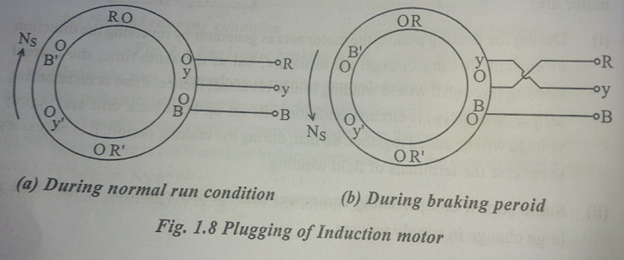
21. With neat sketch explain the Plugging in Series and Shunt Motors?
Plugging : It is a simple method of electric braking, In this method reversing the connections of the armature terminals of a motor, so as to reverse its direction of rotation which will oppose the original direction of rotation of the motor and will bring it to zero speed then mechanical brakes can be applied. At the end of the braking period the supply to the motor is automatically cut off.
DC Series Motor:
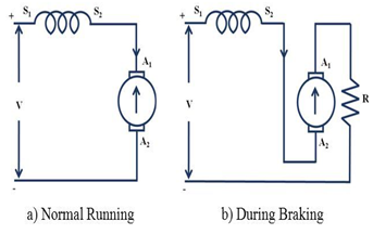
DC Shunt Motor:
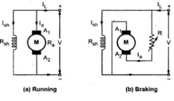
In the normal running position the back emf is nearly equal to applied voltage and opposite in direction, so that a small voltage acts across the armature circuit to drive the normal current through a small resistance of the motor. In the plugging position, When the armature terminal connections are reversed, emf of the machine is in the same direction as that of the applied voltage. The total voltage of V+Eb is available across the armature terminals cause a current I to flow around the circuit. When Eb = V, then the voltage across the armature is 2V, twice of supply voltage acts across the machine circuit and heavy current would flow (about twice the current drawn by the stationary motor on normal rated voltage). Hence to avoid flow of heavy current and limit it to the safer value, it is necessary that switching performing the plugging operation may also re-insert starting resistance and some additional resistance in series with the armature circuit of the motor.
22. With neat sketch explain the Rheostatic Braking of Series and Shunt Motors?
Rheostatic Braking / dynamic braking:
In this type, motor is disconnected from the supply and run as a generator driven by the remaining KE of the equipment, ie by the energy stored in the motor and load which are to be braked. Across this generator is connected the resistive loads which is gradually increased and the generator output is dissipated.ie, braking resistor Rb is connected across the armature as soon as the DC motor is disconnected from the supply mains. The motor now works as a generator, producing the braking torque.
Shunt Motor:
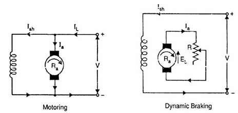
Armature is simply disconnected from the supply and is connected to a resistance in series with it, the field winding remains connected to the supply. The braking torque can be adjusted suitably by varying the resistance in the armature circuit. In case supply fails, the field disappears and there is no braking torque.
Series Motor:
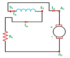
The motor after disconnecting from the supply is made to run as a c series generator. The resistance is inserted in the circuit must be less than the critical resistance otherwise the generator will not be self-exciting. When the series motor is disconnected from the supply, the direction of the armature current is reversed, therefore the field connections must be reversed in order to allow the flux to build up.
23. With neat sketch explain the Regenerative Braking of Series and Shunt Motors?
Regenerative Braking:
Regenerative braking takes place whenever the speed of the motor exceeds the synchronous speed. This baking method is called regenerative baking because here the motor works as generator and supply itself is given power from the load, i.e. motors.
The motor is not disconnected from the supply but remains connected to it and it feed back the braking energy or its KE to the supply system . This method is better than other braking system. This method is used when the load on the motor has overhauling characteristics as in the lowering of the cage of a hoist or the downgrade motion of an electric train. Regeneration takes place when Eb becomes greater than V. This happens when the overhauling load acts as a prime mover and so drives the machines as a generator. Consequently, the direction of armature current and the torque is reversed, hence speed falls until Eb = V. then mechanical brake applied
DC Shunt motor:
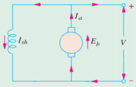
As the speed of the motor increases due to overhauling loads, the induced emf exceeds (Eb > V) the supply voltage and the energy will be fed into the supply system. This will quickly decrease the speed of the motor and can be brought to the rest. This constitutes regenerative braking.
DC Series motor:
In dc series motor, complications arise due to the fact that if the motor act as generator, the reversal of current in the armature would cause a reversal of polarity of the series field and hence the field flux will be neutralized. In order to avoid the neutralization of field flux, Special arrangements are then made to obtain the working of motors.
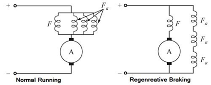
So it use auxillary field windings which are bunched together in parallel and whole bunch is connected in parallel to the main field. So the machine behaves differentially compound generator when regenerate braking takesplace. If there is slight change in the line voltage the shunt Field will immediately cause the increase in the generated emf. This method is also known as French method.
24. With neat sketch explain the Regenerative Braking of Three Phase Induction Motors?
Induction motor act as a generator when running at speed higher than the synchronous speed and it feeds power back to the ac mains ie, Regenerating. The machine will work as an induction generator. The value of slip becomes negative.
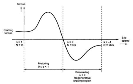
Speed below synchronous, Pole changing method is used for this purpose, If the number of stator poles is increased, synchronous speed will be less than the actual running speed. Machine will work as an induction generator.
25. Explain the Advantages of Electric Traction?
- The electric train system is very clean and neat.
- The system does not require water and coal.
- Electric motors occupy very less area compared to other traction system.
- The maintenance cost and time required is less.
- Coefficient of adhesion is better.
- Cheapest method of traction.
- Less vibration.
- less maintenance cost.
- Rapid acceleration and braking.
- High starting torque.
- It has great passenger carrying capacity at higher speed.
- Free from smoke and few gases, so used for underground and tubular railways.
- Electric Braking is superior to mechanical braking.
- Uniform torque of electric motors reduces the jerking action to the passengers.


Recent Comments