
Familiarisation of Logic Gates and Digital IC’S
FAMILIARISATION OF LOGIC GATES AND DIGITAL ICS
AIM:
To familiarize with logic gate IC packages and to verify the truth tables of the logic gates. Also to familiarize with the digital IC trainer kit.
MATERIALS AND TOOLS REQUIRED:
ICs 7400,7432, 7486, 7408 and Ic trainer kit.
THEORY:
IC Trainer Kit : IC Trainer Kit is an equipment mainly used to test and set up digital circuits while doing experiments. Integrated circuits can be fitted in sockets or breadboard provided in kit. the associated circuits can be set up on the bread board. There are built in voltage source and clock signals in it. The frequency of clock can be selected by turning the knob into different positions. In order to feed mono pulses manually, the deb ounce switch is also provided. A number of select switches are provided to obtain 0 or 1 state voltages for digital inputs. Green and Red LEDs are also provided to represent Low and High states respectively to visualize the digital outputs.
Logic gates: In digital electronics, a gate is logic circuits with one output and one or inputs. Logic gates are available as integrated circuits.
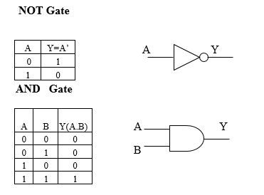
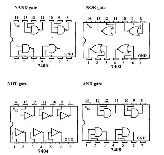
AND gate: the AND gate performs logical multiplication, more commonly known as And operation. The AND gate output will be in high state only when all the inputs are in high state.
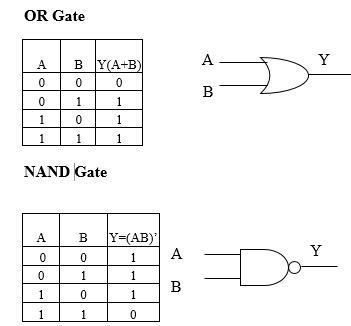
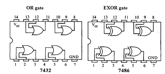
OR gate: It performs logical addition. Its output become high if any of the inputs is in logic high. 7432 is a Quad 2 input OR gate.
NOT gate: It performs basic logic function for inversion or complementary. The purpose of the inverter is to change one logic level to the opposite level. IC 7404 is a Hex inverter.
NAND gate: A NOT gate following an And gate is called NOT-AND or NAND gate.Its output will be low if all the inputs are in high state. 7400 IC is Quad two input NAND gate.
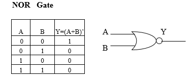
NOR gate: A NOT gate following an OR gate is called NOT-OR or NOR gate. Its output will be in low state if any of its input is in high state. 7402 is a Quad two input NOR gate.
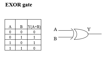
EXOR gate: Its output will be high if and only if one input is in high state. 7486 is a Quad two input EXOR gate.
Circuit Diagram:
PROCEDURE:
- Test all the components in the Ic packages using a digital IC tester. Also assure whether all the connecting wires are in good condition by testing for the continuity using a Multi meter or a trainer kit.
- Verify the dual in line package (DIP) Pinout of the IC before feeding the inputs.
- Set up the circuits and observe the outputs. Enter the input and output stats in truth table corresponding to the input combinations.
RESULT:
Various Logic gate ICs and digital trainer kit are familiarized.


Recent Comments