
Load Characteristics of DC Compound Generator
LOAD CHARACTERISTICS OF DC COMPOUND GENERATOR
AIM:
- To conduct a load test on the given dc compound generator & plot its internal & external characteristics when working in cumulative & differential mode.
APPARATOUS REQUIRED:
| S.No. | Apparatus | Range | Type | Quantity |
| 1 | Ammeter | |||
| 2 | Voltmeter | |||
| 3 | Rheostats | |||
| 4 | SPST Switch | |||
| 5 | Tachometer |
MACHINES DETAILS:
THEORY :
The compounding of a machine is done by adding a few coils in series with the armature coil circuit of a shunt machine. Compound generator, both series and shunt excitation are combined. The shunt winding can be connected either across the armature only (short-shunt connection S) or across armature plus series field (long-shunt connection G). The compound generator can be cumulatively compounded or differentially compounded generator.
When a compound generator has its series field flux aiding its shunt field flux, the machine is said to be cumulative compound. When the series field is connected in reverse so that its field flux opposes the shunt field flux, the generator is then differential compound. The easiest way to build up voltage in a compound generator is to start under no load conditions. At no load, only the shunt field is effective. When no-load voltage build up is achieved, the generator is loaded. If under load, the voltage rises, the series field connection is cumulative. If the voltage drops significantly, the connection is differential compound.
The series excitation aids the shunt excitation. The degree of compounding depends upon the increase in series excitation with the increase in load current.
(i) If series winding turns are so adjusted that with the increase in load current the terminal voltage increases, it is called over-compounded generator. In such a case, as the load current increases, the series field m.m.f. increases and tends to increase the flux and hence the generated voltage. The increase in generated voltage is greater than the IaRa drop so that instead of decreasing, the terminal voltage increases .
(ii) If series winding turns are so adjusted that with the increase in load current, the terminal voltage substantially remains constant, it is called flat-compounded generator. The series winding of such a machine has lesser number of turns than the one in over-compounded machine and, therefore, does not increase the flux as much for a given load current. Consequently, the full-load voltage is nearly equal to the no-load voltage.
(iii) If series field winding has lesser number of turns than for a flat compounded machine, the terminal voltage falls with increase in load current Such a machine is called under-compounded generator.
PRECAUTIONS:
- The field rheostat of motor should be at minimum position.
- The field rheostat of generator should be at maximum position.
- No load should be connected to generator at the time of starting and stopping.
PROCEDURE:
- Connections are made as per the circuit diagram.
- After checking minimum position of DC shunt motor field rheostat and maximum position of DC shunt generator field rheostat, DPST switch is closed and starting resistance is gradually removed.
- Under no load condition, Ammeter and Voltmeter readings are noted, after bringing the voltage to rated voltage by adjusting the field rheostat of generator.
- Load is varied gradually and for each load, voltmeter and ammeter readings are noted.
- Then the generator is unloaded and the field rheostat of DC shunt generator is brought to maximum position and the field rheostat of DC shunt motor to minimum position, DPST switch is opened.
- The connections of series field windings are reversed the above steps are repeated.
- The values of voltage for the particular currents are compared and then the differential and cumulative compounded DC generator is concluded accordingly.
PROCEDURE FOR MEASURING Ra:
- 1. Connections are made as per the circuit diagram.
- Supply is given by closing the DPST switch.
- Readings of Ammeter and Voltmeter are noted.
- Armature resistance in Ohms is calculated as Ra = (Vx1.5) /I
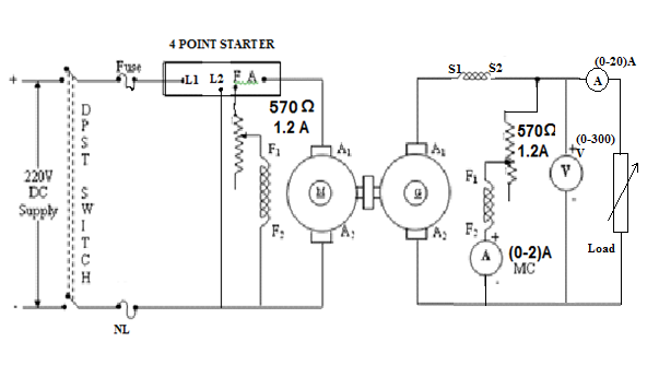
CIRCUIT DIAGRAM
TABULAR COLUMN:
| S.No. | Cumulatively Compounded | Differentially Compounded | |
| V (Volts) | IL (Amps) | V (Volts) | IL (Amps) |


Recent Comments