
Open Circuit Characteristics of Separately Excited Generator
OPEN CIRCUIT CHARACTERISTICS OF SEPERATELY EXCITED GENERATOR
AIM:
- To conduct open circuit test on a separately excited generator and plot the OCC at rated speed and off rated speed. Determine the critical speed and critical resistance of the machine.
APPARATOUS REQUIRED:
| S.No. | Apparatus | Range | Type | Quantity |
| 1 | Ammeter | |||
| 2 | Voltmeter | |||
| 3 | Rheostats | |||
| 4 | SPST Switch | |||
| 5 | Tachometer |
MACHINES DETAILS:
THEORY :
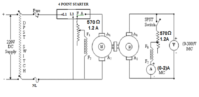
- Connections are made as per the circuit diagram.
- After checking minimum position of motor field rheostat, maximum position of generator field rheostat, DPST switch is closed and starting resistance is gradually removed.
- The machine runs at its rated speed (with the switch open) Note the residual emf on voltmeter. Close the key K and adjust resistance. if the voltmeter reading is increases the connections are correct. Otherwise interchange the connections of the generator field winding terminal C and D.
- Adjust R2 suitably for different values of field current and note the down current and voltage in each step.
- Then cut the rheostat gradually in steps and note down the field current and terminal voltage in each step, continue till the Field current is varied till generated voltage reaches 125% of the rated voltage.
- After bringing the generator rheostat to maximum position, field rheostat of motor to minimum position, SPST switch is opened and DPST switch is opened.
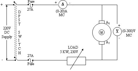
- For finding field resistance, connect the fig 2 as shown in fig. take two or three readings and tabulate it.
PRECAUTIONS:
- The field rheostat of the motor should be in the minimum position at the time of starting and stopping the machine.
- SPST switch should be kept open at the time of starting and stopping the machine.
PROCEDURE:
- Connections are made as per the circuit diagram.
- After checking the minimum position of field rheostat, DPST switch is closed and starting resistance is gradually removed.
- By adjusting the field rheostat, the machine is brought to its rated speed.
- The armature current, field current and voltage readings are noted.
- The field rheostat is then brought to minimum position DPST switch is opened.
PROCEDURE FOR DETERMINING THE RESISTANCE:
- Connections are made as per the circuit diagram.
- Supply is given by closing the DPST switch.
- Readings of Ammeter and Voltmeter are noted.
- Armature resistance in Ohms is calculated as Ra = (Vx1.5) /I
CIRCUIT DIAGRAM
DETERMINATION OF ARMATURE RESISTANCE
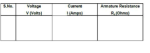
TABULAR COLUMN:


Recent Comments