
OC and SC Test on Single Phase Transformer
O.C AND S.C TESTS ON SINGLE PHASE TRANSFORMER
AIM:
To conduct open circuit and short circuit tests on the given 2.5KVA transformerand predetermine the following:-
- Equivalent circuit as referred to low voltage side
- Equivalent circuit a referred to high voltage side
- Efficiency curve at 0.8 pf lag and lead
- Regulation at unity, lagging and leading power factors
APPARATOUS REQUIRED:
| S.No. | Apparatus | Range | Type | Quantity |
| 1 | Ammeter | |||
| 2 | Voltmeter | |||
| 3 | Rheostats | |||
| 4 | SPST Switch | |||
| 5 | Tachometer |
MACHINES DETAILS:
THEORY :
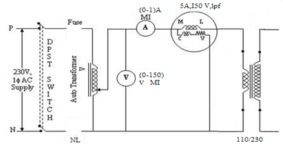
Open Circuit test
This test is usually conducted on the low voltage side side of the transformer. It is conducted to determine the core loss(iron loss or no load loss). The low voltage side of the transformer is supplied at rated voltage with the high voltage side left open. The current, voltage and power on the input side is noted. Since the no-load primary current is small(2-10% of the rated current) the copper losses in the primary winding can be neglected and the power loss read by the wattmeter is the core loss of the transformer. Since the flux linking with the core is constant at all loads, the core loss remains same for all loads. The parameters R0 and X0 (the shunt branch) are determined using this test.
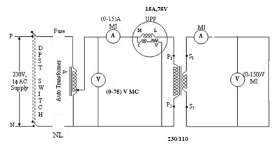
Short Circuit test
The short circuit test is conducted to determine the full load copper loss and the equivalent resistance and leakage reactance referred to the winding in which the test is conducted. The test is conducted on the high voltage side with the low voltage side short circuited by a thick conductor. A low voltage just enough to circulate the rated current of the transformer is supplied to the transformer. The voltage supplied is usually only 5-10% of the normal supply voltage and so the flux linking with the core is small. Thus core losses can be neglected and the wattmeter reading gives the full load Cu loss of the transformer
PRECAUTIONS:
PROCEDURE:
Open Circuit test
- Connections are made as shown in the connection diagram 1.
- The high voltage side is left open. The supply is switched on with the auto transformer in the Minimum position.
- The auto transformer is gradually varied till the voltmeter reads the rated voltage of the Primary side of the transformer. The corresponding ammeter and wattmeter readings are noted down.
Short Circuit test
- Connections are made as shown in the diagram 2.
- The low voltage side is short circuited. Supply is switched on with the auto transformer in the minimum position.
- The auto transformer is gradually varied till the ammeter reads the rated current of the Transformer on the high voltage side.
CIRCUIT DIAGRAM
OPEN CIRCUIT TEST
SHORT CIRCUIT TEST
TABULAR COLUMN:
- OC TEST
| V0 (volt) | I0 (Ampere) | W0(watt) |
- SC TEST
| Vsc (volt) | Isc(Ampere) | Wsc(watt) |
- REGULATION
| Lagging power factor | Leading power factor | ||||
| sl.no. | cosɸ | Regulation | sl.no. | cosɸ | Regulation |


Recent Comments