
Ramp Controlled Trigger Circuit for a Thyristor
TRIGGER CIRCUIT USING RAMP CONTROL
AIM:
To design and set up a ramp controlled trigger circuit for a thyristor in a single phase half wave controlled rectifier.
EQUIPMENTS AND COMPONENTS REQUIRED:
| Sl No | Apparatus/Tool | Specification | Quantity |
| 1 | SCR, TTL IC 74121 | ||
| 2 | Ammeters- | ||
| 3 | Power Supply- | ||
| 4 | Wattage Resistors- | ||
| 5 | Voltmeters- | ||
| 6 | Potentiometers | ||
| 7 | Capacitor | ||
| 8 | SCR, | ||
| 9 | Transformer | ||
| 10 | Bread Board |
THEORY:
For phase controlled rectifier, the trigger pulse must be synchronized with the main supply. In ramp control circuit, the ramp generator produces a saw tooth waveform in synchronism with main supply. This ramp is compared with a DC level in an opamp comparator. The output of the comparator is the trigger pulse which may be directly applied or through one amplifier and pulse transformer to the thyristor gate. The trigger delay can be varied by varying the dc level applied to the comparator.
ZCD: The closed loop gain of the op-amp is selected high to get a square wave as output when the input signal crosses zero.
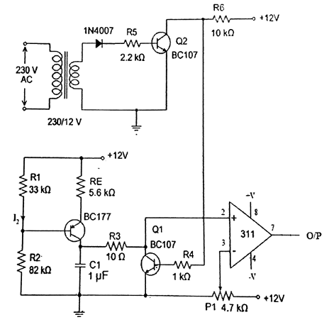
CIRCUIT DIAGRAM:
PROCEDURE:
Design the ramp control circuit as per the design given above. Choose 0.5mA as the charging current of the capacitor C in the ramp generator. Set up the circuit and test the performance.
RESULT:
A ramp control trigger circuit for a thyristor in a single phase half wave controlled rectifier has been designed and set up.


Recent Comments