
RC Phase Shift Oscillator
AIM
To set up an RC phase shift oscillator and to observe the sinusoidal output waveform.
COMPONENTS AND EQUIPMENTS REQUIRED
- POWER SUPPLY 2 V 1 NO
- TRANSISTOR BC 107 1 NO
- RESISTORS 4.7 KΩ , 3 NO
- 10 K, 2.2K, 47K, 680 Ω 1 each
- CAPACITORS 0.01μF
- 22μF , 1μF 1 each
- BREAD BOARD 1 NO
- CONNECTING WIRES AS REQUIRED
THEORY
An oscillator is an electronic circuit for generating an ac signal voltage with a dc supply as the only input requirement. The frequency of the generated signal is decided by circuit constants. An oscillator requires an amplifier and a positive feed back from out put to input. The barkhausen criterion for sustained oscillation is (1) loop gain=1 ie Aβ =1 , where A is the gain and β is the feed back factor (2) Total phase shift = 360 degree. A CE amplifier introduces a 180degree phase shift and feed back network another 180 degree. Feed back network consist of 3 RC network each produces a 60 degree and hence total 180 degree. Frequency of oscillation f = 1/ 2ΠRC√6
PROCEDURE
1. Set up the amplifier part of the oscillator and test the dc conditions.
2. Connect the feedback network and observe the sine wave on CRO and measure its amplitude and frequency
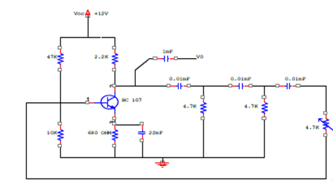
CIRCUIT DIAGRAM
RESULT
Observed the sinusoidal wave form at the output of oscillator


Recent Comments