
Regulation of Alternator by EMF Method
REGULATION OF 3–PHASE ALTERNATOR BY EMF AND MMF METHODS
AIM:
To predetermine the regulation of 3-phase alternator by EMF and MMF methods and also draw the vector diagrams.
APPARATOUS REQUIRED:
| S.No. | Apparatus | Range | Type | Quantity |
| 1 | Ammeter | |||
| 2 | Voltmeter | |||
| 3 | Rheostats | |||
| 4 | SPST Switch | |||
| 5 | Tachometer |
MACHINES DETAILS:
THEORY :
The regulation of a 3-phase alternator may be predetermined by conducting the Open Circuit (OC) and the Sort Circuit (SC) tests. The methods employed for determination of regulation are EMF or synchronous impedance method, MMF or Ampere Turns method and the ZPF or Potier triangle method. In this experiment, the EMF and MMF methods are used. The OC and SC graphs are plotted from the two tests. The synchronous impedance is found from the OC test. The regulation is then determined at different power factors by calculations using vector diagrams. The EMF method is also called pessimistic method as the value of regulation obtained is much more than the actual value. The MMF method is also called optimistic method as the value of regulation obtained is much less than the actual value. In the MMF method the armature leakage reactance is treated as an additional armature reaction. In both methods the OC and SC test data are utilized.
PRECAUTIONS:
- The motor field rheostat should be kept in the minimum resistance position.
- The alternator field potential divider should be kept in the minimum voltage position.
- Initially all switches are in open position.
PROCEDURE:
- Note down the name plate details of the motor and alternator.
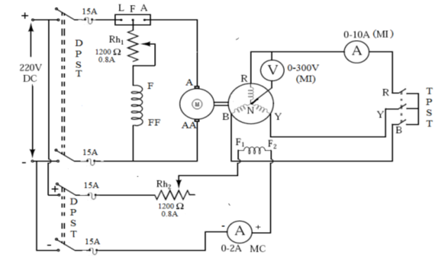
- Connections are made as per the circuit diagram.
- Switch ON the supply by closing the DPST switch
- Using the Three point starter, start the motor to run at the synchronous speed by adjusting the motor field rheostat.
- Conduct Open Circuit test by varying the potential divider for various values of field current and tabulate the corresponding Open Circuit Voltage readings.
- Conduct Short Circuit test by closing the TPST switch and adjust the potential divider to set the rated armature current and tabulate the corresponding field current.
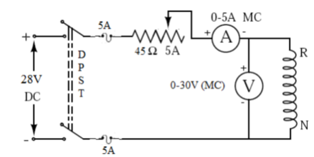
- The Stator resistance per phase is determined by connecting any one phase stator winding of the alternator as per the circuit diagram using MC voltmeter and ammeter of suitable ranges.
PROCEDURE TO DRAW GRAPH FOR EMF METHOD:
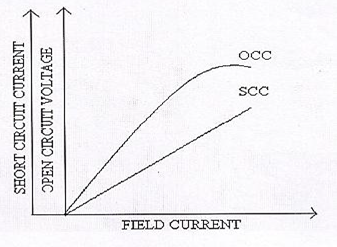
- Draw the Open Circuit Characteristic curve (Generated Voltage per phase VS Field current).
- Draw the Short Circuit Characteristics curve (Short circuit current VS Field current)
- From the graph find the open circuit voltage per phase (E1 (ph) for the rated short circuit current (Isc).
- By using respective formulae find the Zs, Xs, Eo and percentage regulation.
PROCEDURE TO DRAW GRAPH FOR MMF METHOD:
- Draw the Open Circuit Characteristic curve (Generated Voltage per phase VS Field current).
- Draw the Short Circuit Characteristics curve (Short circuit current VS Field current)
- Draw the line OL to represent
CIRCUIT DIAGRAM
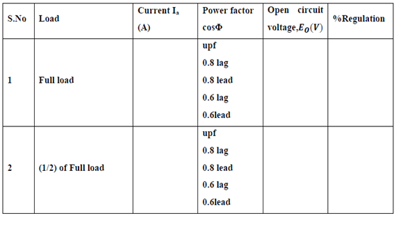
TABULAR COLUMN:
SAMPLE GRAPH


Recent Comments