
Electrical Workshop Practice Lab Manual
EXPERIMENT NO: 1
WIRING OF SIMPLE LIGHT CIRCUIT FOR CONTROLLING LIGHT/FAN POINT
Aim
To wire up a circuit with one lamp controlled by one switch in surface conduit system of
wiring as per given layout and check the conditions.Also Prepare the estimation.
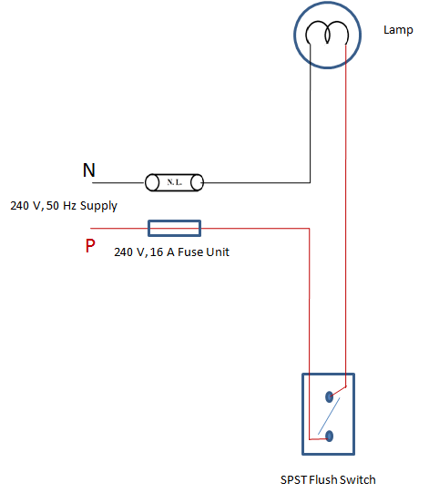
CONDITIONS
S1↑ L1 Dark
S1↓ L1 Bright
Tools required
Screwdriver, line tester, cutting plier, wire stripper, hammer, hacksaw, poker
Estimation
| Sl.No | Name of Material | Specification | Quantity | Unit |
| 1 | PVC Conduit | 20 mm | ||
| 2 | PVC insulated Copper wire | 1 mm2, , 1100 V grade | ||
| 3 | Flush Type SPST Switch | 6A, 240 V | ||
| 4 | Switch box(Gang Box) | 75×50×25 mm | ||
| 5 | Steady batten lamp holder | 6 A, 250 V | ||
| 6 | Incandescent Bulb | 60 W, 240 V | ||
| 7 | Saddle clips | 20 mm | ||
| 8 | PVC Round block | 75 X 25 mm | ||
| 9 | 3 way Junction box | 20 mm | ||
| 10 | Neutral Link | 6 A, 240 V | ||
| 11 | Kitkat type fuse unit | 6 A, 240 V | ||
| 12 | Screws | 13×4mm | ||
| 16×8mm | ||||
| 30×8mm | ||||
Procedure
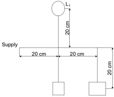
- Cut the Conduits in the required length (20cm) using Hack saw.
- Fix the conduits ,junction box ,switch box in required positions as per the lay out using saddles and screws.
- Run the wire through conduits, as per the given circuit diagram & then fix the Round block,switches,holder in required positions using screws.
- Check the circuit before applying the supply
- Give the single phase supply through a fuse and neutral link
- Check the conditions
LAY OUT
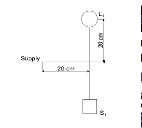
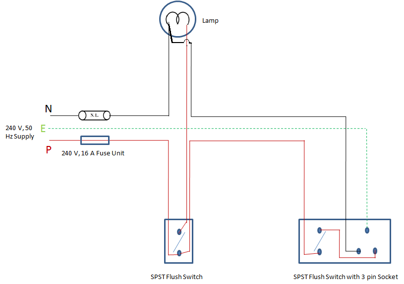
CIRCUIT DIAGRAM
Result:
EXPERIMENT NO: 2
WIRING OF LIGHT/FAN CIRCUIT USING TWO WAY SWITCHES (STAIRCASE WIRING)
Aim
To wire up a circuit with one lamp controlled simultaneously from 2 places as per the given
layout diagram in surface conduit system of wiring & check the conditions .Also Prepare the Estimation to finish the work.
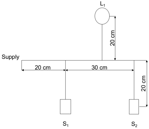
CONDITIONS
S1↑ S2↑ L Bright
S1↑ S2↓ L Dark
S1↓ S2↑ L Dark
S1↓ S2↓ L Bright
Tools Required:
Screw driver, line tester, pocker ,hammer, wire stripper, plier, Hack saw.
Estimation
| Sl.No | Name of Material | Specification | Quantity | Unit |
| 1 | PVC Conduit | 20 mm | ||
| 2 | PVC insulated Copper wire | 1 mm2, , 1100 V grade | ||
| 3 | Flush Type SPST Switch | 6A, 240 V | ||
| 4 | Switch box(Gang Box) | 75×50×25 mm | ||
| 5 | Steady batten lamp holder | 6 A, 250 V | ||
| 6 | Incandescent Bulb | 60 W, 240 V | ||
| 7 | Saddle clips | 20 mm | ||
| 8 | PVC Round block | 75 X 25 mm | ||
| 9 | 3 way Junction box | 20 mm | ||
| 10 | Neutral Link | 6 A, 240 V | ||
| 11 | Kitkat type fuse unit | 6 A, 240 V | ||
| 12 | Screws | 13×4mm | ||
| 16×8mm | ||||
| 30×8mm | ||||
Procedure :
- Cut the Conduits in the required length (20cm) using Hack saw.
- Fix the conduits ,junction box ,switch box in required positions as per the lay out using saddles and screws.
- Run the wire through conduits, as per the given circuit diagram & then fix the Round block,switches,holder in required positions using screws.
- Check the circuit before applying the supply
- Give the single phase supply through a fuse and neutral link
- Check the conditions
Result :
Layout
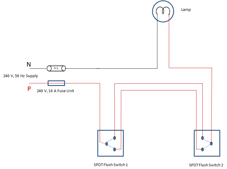
Circuit Diagram
RESULT
EXPERIMENT NO: 3
WIRING OF FLUORESCENT LAMPS AND LIGHT SOCKETS
Aim
To wire up a flouroscent lamp with a choke and starter connected by a switch in PVC conduit system of wiring. Also prepare the estimation.
Tools
Hammer, Screw driver, wire stripper, line tester, pocker, and knife
Estimation
Procedure
- Cut the conduits in the required length using Hacksaw.Then fix the conduit, junction box, switch box in required positions as per layout.
- Run the wire through the conduit as per the given circuit diagram and then fix the round block.
- Connect the phase from ceiling rose to ballast and other end of the ballast is connected to the tube electrode. Glow type starter is connected.
- Check the circuit before applying the supply.
Result:
EXPERIMENT NO: 4
WIRING OF POWER CIRCUIT FOR CONTROLLING POWER DEVICES
Aim
To wire up a circuit with one lamp controlled by one switch with addition of plug point in surface conduit system of wiring as per the given layout & check the conditions.Also prepare the estimation.
CONDITIONS
S1↑ S2↑ L1 Dark P Off
S1↓ S2↓ L1 Bright P On
Tools required
Screw driver, line tester, cutting plier, stripper, hammer, hack saw, pocker
Estimation
| Sl.No | Name of Material | Specification | Quantity | Unit |
| 1 | PVC Conduit | 20 mm | ||
| 2 | PVC insulated Copper wire | 1 mm2, , 1100 V grade | ||
| 3 | Flush Type SPST Switch | 6A, 240 V | ||
| 4 | Switch box(Gang Box) | 75×50×25 mm | ||
| 5 | Steady batten lamp holder | 6 A, 250 V | ||
| 6 | Incandescent Bulb | 60 W, 240 V | ||
| 7 | Saddle clips | 20 mm | ||
| 8 | PVC Round block | 75 X 25 mm | ||
| 9 | 4 way Junction box | 20 mm | ||
| 10 | Neutral Link | 6 A, 240 V | ||
| 11 | Kitkat type fuse unit | 6 A, 240 V | ||
| 12 | Screws | 13×4mm | ||
| 13 | 16×8mm | |||
| 14 | 30×8mm | |||
| 15 16 | Bend | 20mm | ||
| 3 pin plug point | 6A,240 V | |||
Procedure
- Cut the Conduits in the required length (20cm) using Hack saw.
- Fix the conduits ,junction box ,switch box in required positions as per the lay out using saddles and screws.
- Run the wire through conduits, as per the given circuit diagram & then fix the Round block,switches,holder in required positions using screws.
- Check the circuit before applying the supply
- Give the single phase supply through a fuse and neutral link
- Check the conditions
Layout
Result :
EXPERIMENT NO: 5
GODOWN WIRING
Aim
To wire up a circuit with three lamps controlled by three switches in surface conduit system of wiring as per the given layout & check the conditions .Also Prepare the Estimation to finish the work.
CONDITIONS
S1 S2 S3 L1 L2 L3
↑ ↑ ↑ OFF OFF OFF
↓ ↑ ↑ ON OFF OFF
↓ ↓ ↑ OFF ON OFF
↓ ↓ ↓ OFF OFF ON
Tools
Screw driver, line tester, poker ,hammer, wire stripper, plier, Hack saw.
Estimation
| Sl.No | Name of Material | Specification | Quantity | Unit |
| 1 | PVC Conduit | 20 mm | ||
| 2 | PVC insulated Copper wire | 1 mm2, , 1100 V grade | ||
| 3 | Flush Type SPST Switch | 6A, 240 V | ||
| 4 | Switch box(Gang Box) | 75×50×25 mm | ||
| 5 | Steady batten lamp holder | 6 A, 250 V | ||
| 6 | Incandescent Bulb | 60 W, 240 V | ||
| 7 | Saddle clips | 20 mm | ||
| 8 | PVC Round block | 75 X 25 mm | ||
| 9 | 3 way Junction box | 20 mm | ||
| 10 | Neutral Link | 6 A, 240 V | ||
| 11 | Kitkat type fuse unit | 6 A, 240 V | ||
| 12 | Screws | 13×4mm | ||
| 16×8mm | ||||
| 13 | Flush Type SPDT Switch | 30×8mm | ||
| 6A, 240 V | ||||
Procedure:
- Cut the Conduits in the required length (20cm) using Hack saw.
- Fix the conduits ,junction box ,switch box in required positions as per the lay out using saddles and screws.
- Run the wire through conduits, as per the given circuit diagram & then fix the Round block,switches,holder in required positions using screws.
- Check the circuit before applying the supply
- Give the single phase supply through a fuse and neutral link
- Check the conditions
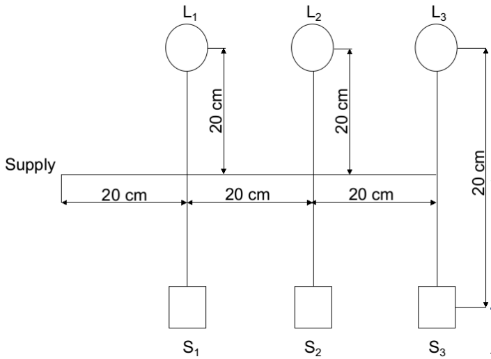
LAYOUT
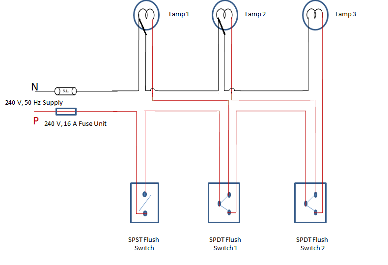
CIRCUIT DIAGRAM
Result :
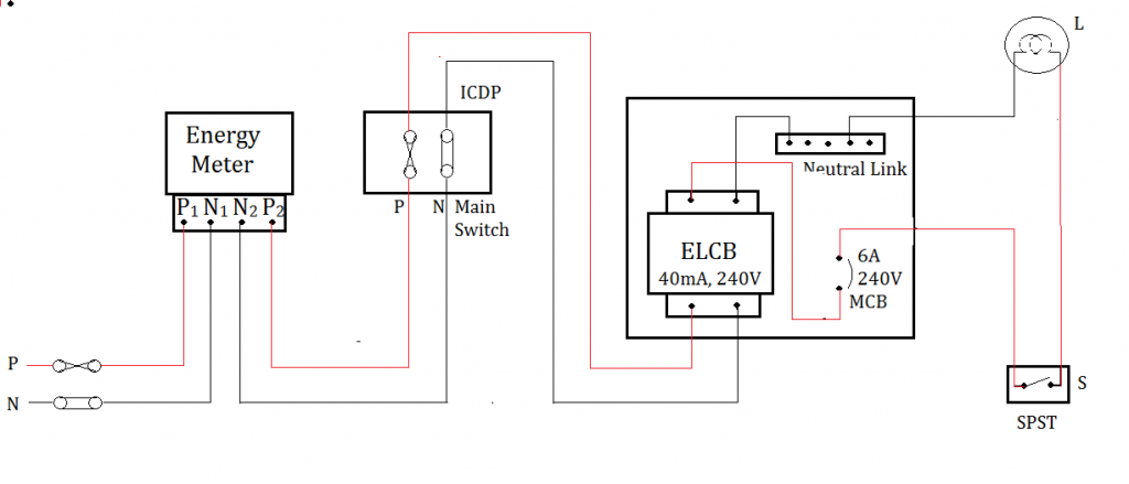
EXPERIMENT NO: 7
WIRING OF POWER DISTRIBUTION ARRANGEMENT USING SINGLE PHASE MCB, DISTRIBUTION BOARD WITH ELCB, MAIN SWITCH AND ENERGY METER
Aim
To design and wire up the circuit of main board and a consumer board having ELCB and MCB for a bed room having one light point. Work is to be done in PVC conduit system as per the
given layout and prepare suitable estimation
Tools required
Pocker, hammer, screw driver, wire stripper, plier, hack saw, and line tester
Materials required
Procedure
- The components are laid on the board and arrange according to the connection diagram
- The whole arrangement is centralised
- Draw wire through the pipes and connection are made in main board and consumer board
- Neutral and phase wire are connected and connections are taken to sub-circuit
CIRCUIT DIAGRAM
Result


Recent Comments