
Ring and Johnson Counters
RING AND JOHNSON COUNTERS
AIM:
To design and set up four bit Johnson and ring counters .
MATERIALS AND TOOLS REQUIRED:
ICs 7476, 7474 and trainer kit and digital trainer kit, Power supply.
THEORY:
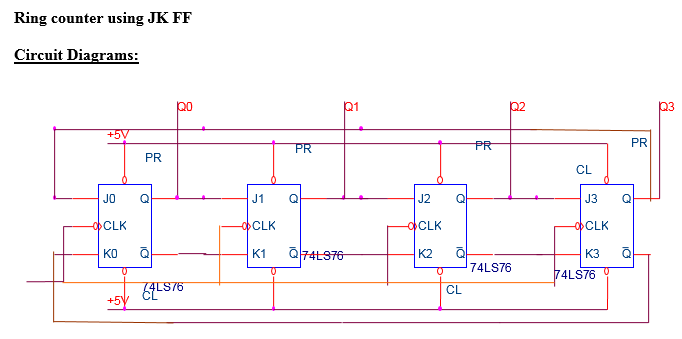
Ring counter and Johnson counter are basically Shift registers. It is constructed using JK flip flops by connection Q and Q’ outputs one from the flip flop to the J and K inputs of the next flip flop. The outputs of the final flip flop are connected to the inputs of the first flip flop.
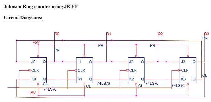
Johnson counter The modulo number of a ring counter can be doubled by making a small change in the ring counter circuit. The Q’ and Q outputs of the last flip flop are connected to the J and K inputs of the first flip flop respectively.
Circuit Diagram:
PROCEDURE:
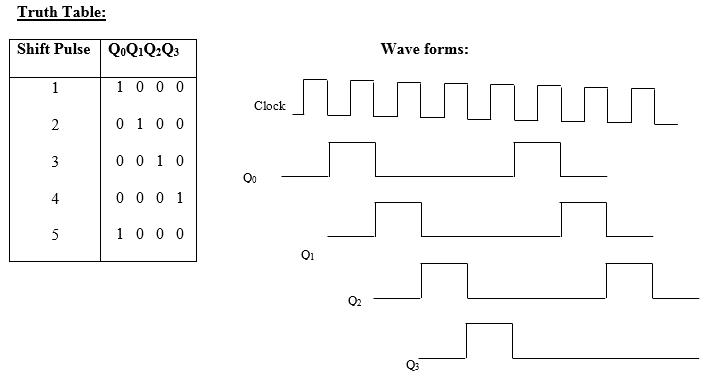
- Set up the ring counter and set any Q output using PRESET and apply mono pulses using d-ebouncer switch n the trainer kit to the CLK input.
- Note down the states of the ring counter outputs on the truth table for successive clocks.
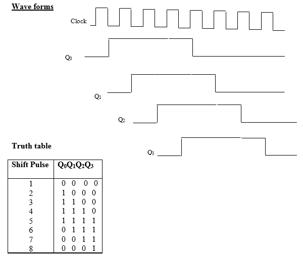
- Repeat the steps 1 and 2 for the Johnson counter.
RESULT:
Four bit Johnson and ring counters are designed.


Recent Comments