
UJT Relaxation Oscillator
AIM
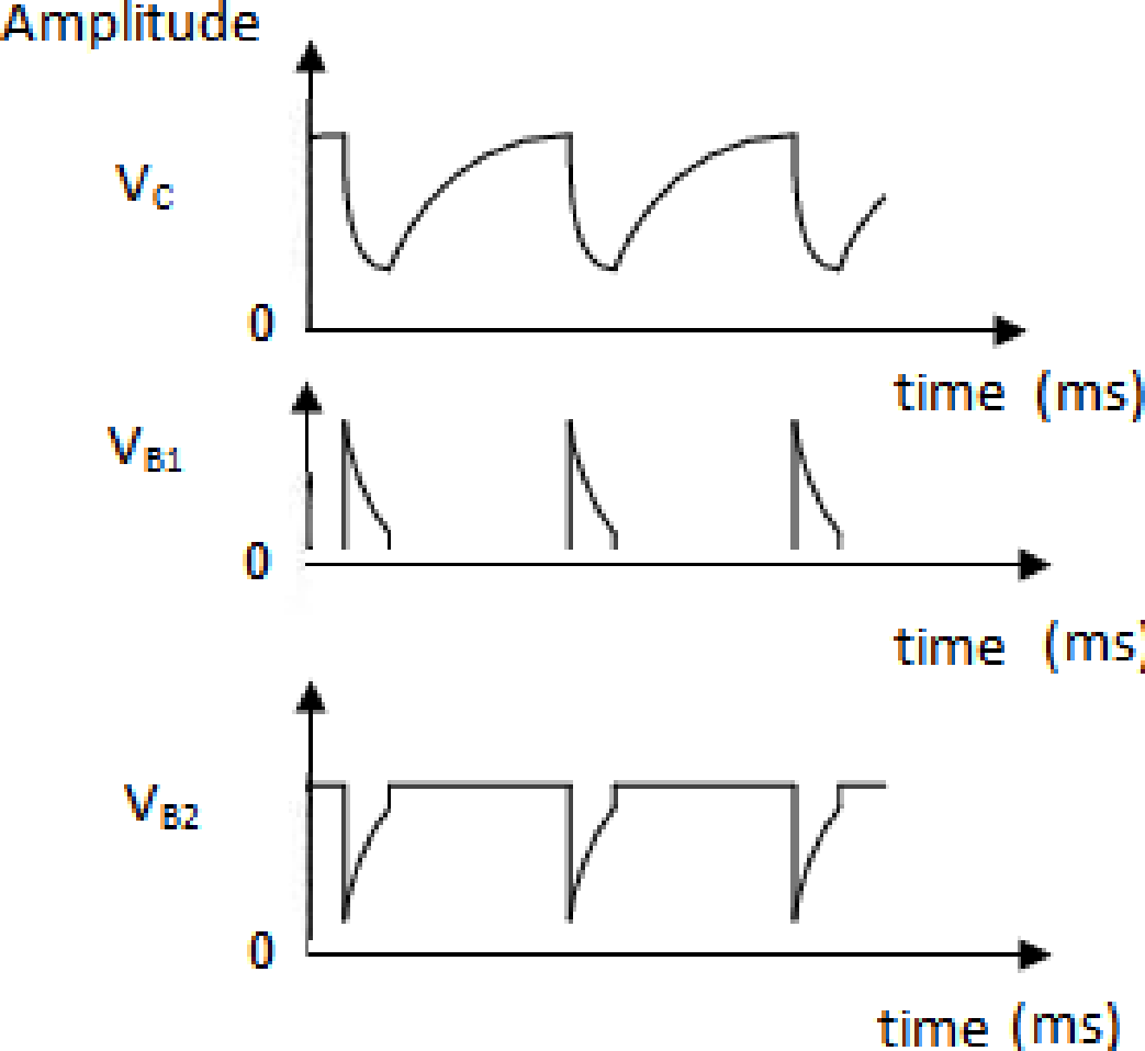
To construct a UJT relaxation oscillator and plot the wave forms at emitter, base 1 and base 2.
COMPONENTS AND EQUIPMENTS REQUIRED
- Resistors 100 Ω 2 nos.
- Capacitor 0.1 μF 1 no.
- UJT 2N2646 1 no.
- Power supply 10 V DC 1 no.
- Oscilloscope 0 to 20 MHz 1 no.
- Multimeter 1 no.
- Breadboard 1 no.
- Connecting wires
THEORY:
UJT is a unipolar device. It is constructed using an N type silicon bar on which a P type silicon material is doped. It has three terminals namely base1 (B1), base2 (B2) and emitter (E). The RC circuit associated with UJT will function as a relaxation oscillator. The sharp pulse available from the circuit can be used as trigger pulse for various applications. Once the power supply is switched ON, Capacitor C charges through R towards VBB. Then the voltage across the capacitor reaches Vp (= ηVBB+ Vd), where η = 0.63, Vd = 0.7V, UJT turns ON and it enters a negative resistance region. The capacitor rapidly discharges through UJT, since it then offers very low resistance. This sudden discharge develops a sharp pulse at B1. When the capacitor voltage reaches valley voltage (Vv) of UJT it turns OFF. This enables the capacitor to charge again and repeat the cycle.
PROCEDURE
- Check the given components and assemble in a bread board as per circuit.
- Connect the output of the circuit to an oscilloscope and Switch ON the power supply
- Plot waveforms
CIRCUIT DIAGRAM

OBSERVATIONS
RESULT
Constructed an UJT relaxation oscillator and plot the wave forms at emitter, base1 and base2.


Recent Comments