
Single Phase fully Controlled Bridge Rectifier Converter
SINGLE PHASE FULLY CONTROLLED BRIDGE CONVERTER
AIM:
To set up a single phase fully controlled bridge converter and conduct experiment in the setup to obtain
- The waveforms across load and thyristor for α= 600 corresponding to the discontinuous mode of operation.
- The load current waveforms for α= 600 corresponding to discontinuous mode of operation.
- The average output voltage α= 600 corresponding to continuous conduction.Verify with theoretical value.
EQUIPMENTS AND COMPONENTS REQUIRED:
| Sl No | Apparatus/Tool | Specification | Quantity |
| 1 | Converter | ||
| 2 | SCR | ||
| 3 | Power Supply- | ||
| 4 | Wattage Resistors- | ||
| 5 | Voltmeters- | ||
| 6 | Potentiometers | ||
| 7 | Capacitor | ||
| 8 | SCR, | ||
| 9 | Transformer | ||
| 10 | Bread Board |
CIRCUIT DIAGRAM:
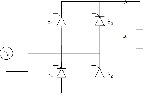
PROCEDURE:
Connections are made as in figure. The autotransformer is adjusted so that the input voltage is 60 V. The firing angle of the thyristors is varied by varying the pot in the firing module. If the thyristors do not fire interchange the input connections to the bridge. The required waveforms are plotted.
RESULT:
A single phase fully controlled bridge converter has been setup. the waveforms across load and thyristor for for α= 600 has obtained corresponding to discontinuous and continuous mode of operation.


Recent Comments