
UJT Firing Circuit
UJT FIRING CIRCUIT
AIM:
- To design and set up a UJT firing circuit for a single phase half wave controlled rectifier or single phase ac regulator.
EQUIPMENTS AND COMPONENTS REQUIRED:
| Sl No | Apparatus/Tool | Specification | Quantity |
| 1 | UJT | ||
| 2 | Ammeters- | ||
| 3 | Power Supply- | ||
| 4 | Wattage Resistors- | ||
| 5 | Voltmeters- | ||
| 6 | Potentiometers | ||
| 7 | Capacitor | ||
| 8 | SCR, | ||
| 9 | Transformer | ||
| 10 | Bread Board |
THEORY:
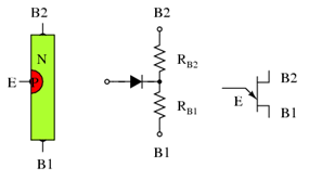
The UJT is atwo layer pn device with three terminals. The terminals are called emitter (E), base-1 (B1) and base-2 (B2). It consists of an n type silicon bar with ohmic contacts for the two base terminals. A single p type emitter junction is formed by alloying a p type material on the side of the silicon bar. Its structure, equivalent circuit and symbol are shown in figure (i).
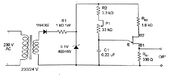
CIRCUIT DIAGRAM:
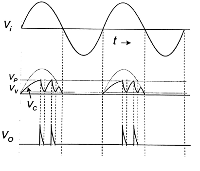
Sample Wave form :
PROCEDURE:
The UJT trigger circuit is set up. The supply is stepped down to a suitable value to get the synchronizing signal, which is fed to the triggering circuit. The waveforms at various stages are observed on the CRO for different values of firing angle.
RESULT:
A UJT firing circuit for single phase half wave controlled rectifier (single phase ac regulator) has been designed, set up and the waveforms have been plotted.


Recent Comments