
Speed control (phase control) using DIAC and TRIAC
AIM
To set up and study the phase control circuit using triac and there by voltage control using diac.
COMPONENTS AND EQUIPMENTS REQUIRED
- Diac DB3ST 1 NO
- Triac BT136 1 NO
- Fan 230V , 100W 1 NO
- Resistor 2.2K , 10K 1 NOS EACH
- Potentiometer 100k 1 NO
- Capacitor 0.33 mfd, 400v 2 NOS
THEORY:
Alternatively voltage controller converts the input voltage to a variable voltage at the same frequency. As the input voltage increases –vely or +vely, the capacitor C is charged through the load resistor R1 and potentiometer. When the capacitor voltage exceeds the break down voltage, the diac is turns on. The capacitor now discharge through the diac and it is appear the +ve pulse across the gate of triac turning it on. This allow AC power flow across the bulb, a similar operation across into the –ve half cycle. The delay after which the triac turned on determining by the charging rate of capacitor and hence by potentiometer.
PROCEDURE
- Check the all given or collected component using multimeter.
- Assemble them on breadboard as shown in figure.
- Connect the bulb to the MT2 of triac Connect the 230v supply to the circuit.
- Observe the light of bulb when varying the potentiometer.
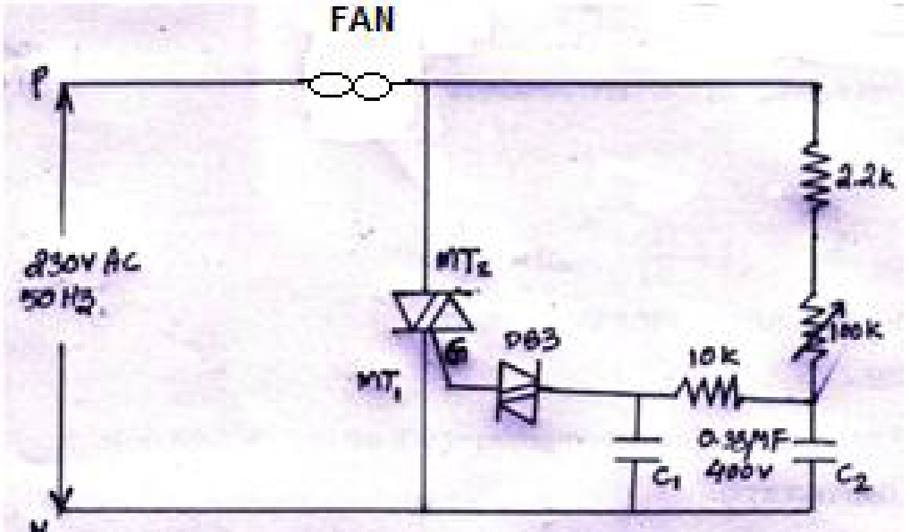
CIRCUIT DIAGRAM
RESULT:
Constructed And studied the phase control circuit uing triac.


Recent Comments