
Phase Locked Loops
PHASE LOCKED LOOPS
AIM:
To study the PLL IC NE 565 and to determine the lock in range and capture range for a free running frequency of 2.5 kHz.
EQUIPMENTS AND COMPONENTS REQUIRED:
| Sl No | Apparatus/Tool | Specification | Quantity |
| 1 | PLL IC 56 | ||
| 2 | SCR | ||
| 3 | Power Supply- | ||
| 4 | Wattage Resistors- | ||
| 5 | Voltmeters- | ||
| 6 | Potentiometers | ||
| 7 | Capacitor | ||
| 8 | SCR, | ||
| 9 | Transformer | ||
| 10 | Bread Board |
THEORY:
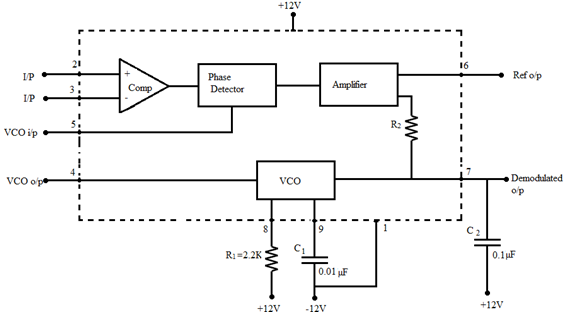
A PLL consists of a phase detector, a low pass filter, an error amplifier and a voltage controlled oscillator. VCO is a free running multivibrator and operates at a set frequency f0, called free running frequency. If an input signal frequency, fs is applied to PLL, the phase detector compares the phase and frequency of the incoming signal to that of the output of VCO. If the two signals differ in frequency or in phase, an error voltage is generated. The high frequency components are removed by the low pass filter and the difference frequency component is amplified and applied as control voltage to VCO. This signal shifts the VCO frequency in a direction to reduce the difference between input and output frequencies. If fs= f0, the circuit is said to be locked. Once locked, PLL tracks the frequency changes of the input signal. Thus PLL goes through three stages.
- Free running stage, Capture stage, Locked stage
Phase Locked Loop is an important block of linear systems. It is a technique for electronic frequency control. Applications are satellite communication systems, air borne navigational systems, FM communication systems, computers etc.
Lock in Range: The range of frequencies over which the PLL can maintain lock with the incoming signal is called lock in range.
Capture range: The range of frequencies over which the PLL can acquire lock with an input signal is called capture range.
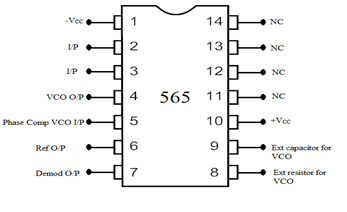
PIN DIAGRAM:
BLOCK DIAGRAM:
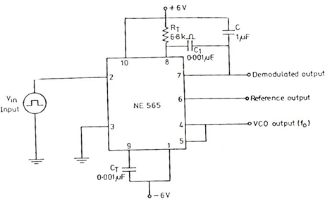
CIRCUIT DIAGRAM:
PROCEDURE:
Circuit is set up. First the free running frequency of the oscillator is to be determined. The pin no 2 and 3 are shorted and connected to the ground. The VCO output is observed at pin no 4 and the free running frequency is measured.
To get the lock range and capture range, the VCO output is given to the phase detector (connect pin no 4 and 5 together). The input signal is given to the pin no 2 and pin no 3 is grounded. The phase detector compares the input signal with VCO output, any difference in phase is amplified and fed back to VCO, which adjust the VCO output frequency to be equal to input signal frequency. Vary the input signal frequency and determine the range of frequencies in which the two signals are locked.
RESULT:
The PLL IC 565 was studied and lock in range and capture range for a free running frequency of 2.5KHz is found.


Recent Comments