
Asynchronous Counters
ASYNCHRONOUS COUNTERS
AIM:
To set up the following counters using JK FF
- 4 bit binary up counter
- 4 bit binary down counter
- Decade counter.
- 3 bit up/down counter using mod control
MATERIALS AND TOOLS REQUIRED:
ICs 7476, 7400, digital trainer kit, Power supply.
THEORY:
A counter is a circuit that produces a set of unique output combinations in relation to the no: of applied input pulses. The no: of unique outputs of a counter is known as its modulus or mod number.
In asynchronous counters, the flip flops are not given clock simultaneously. Four flip flops must be used in toggle mod to count 16 states.
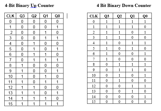
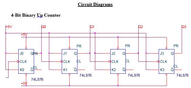
(1) 4 bit up counter: All outputs are clocked by the Q output of the proceeding FF. JK inputs are connected to a high state. 7476 is a dual JK master slave FF with preset and clear. A ripple counter comprising of n flip flops can be used to count up to 2n pulses. A 4 FF circuit gives a maximum count of 24 = 16. With the application of first clock pulse, Q0 changes from 0 to 1.Q1, Q2, Q3 remains unaffected. With the 2nd clock pulse, Q0 becomes 0 and Q1 becomes 1.At the arrival of the 15th clock pulse all the Q outputs becomes 1.At the 16th clock pulse all Q outputs become reset and cycle repeats.
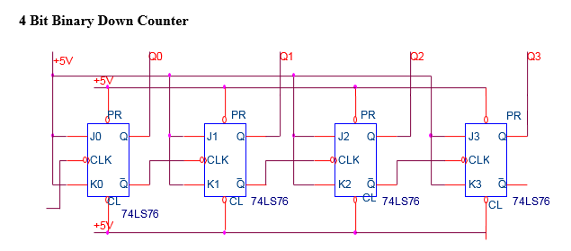
(2) 4 bit binary down counter: In this counter, all outputs are clocked by the Q output of the proceeding FF. The outputs are taken from the Q outputs. Initially all Q outputs are set.
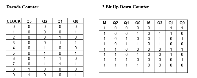
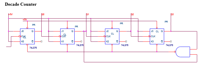
(3) Decade counter: The circuit of the decade counter is similar to the 4 bit ripple counter ,but with the aid of a logic circuit the count is limited to 9.As soon as the count 1010 takes place, a NAND gate clears the flip flops and counting restarts from 0.
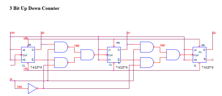
(4) 3 bit up/down counter: The direction of counting sequence is made dependent on a mode control input. A logic circuit connected between the flip flop does a mere job of connecting either if the Q or Q .When mode control is 1 Q outputs are connected to the clock inputs of the succeeding flip flops .If mode control is 0, Q outputs are connected to the clock inputs.
Circuit Diagram:
PROCEDURE:
The circuit is set up on the breadboard in the IC trainer kit. The clock pulse is applied and the clear and preset inputs are kept high. The counting sequence is noted.
RESULT:
4 bit binary up counter 4 bit binary down counter, decade counter, 3 bit up/down counter using mod control was set up sing JK flip flop and the counting sequence was noted.


Recent Comments