
Computer Aided Drafting (CAD) Lab Manual
EXPERIMENT NO : 1
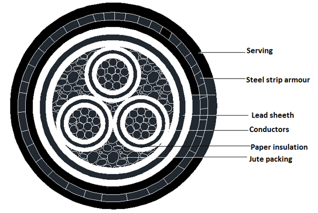
CROSS LINKED POLYETHYLENE CABLE
AIM:
Draw the cross sectional elevation of XLPE Cable using Auto cad software.
PROCEDURE:
The following general commands are used to draw the cross sectional view of XLPE cable in Auto cad.
Step 1: Set the limits of the drawing screen.
Step 2: PUT ORTHOON where ever necessary.
Step 3: Using OSNAP function.
Step 4: Draw circles of given dimension using circle command.
Step 5: Use polar Array.
Step 6: Use Donut Command.
Step 7: Use batch and copy Command.
Step 8: Use Text Command and mark the parts of the figure.
Step 9: Command: – q Save.
RESULT:
The cross-section of XLPE Cables is drawn by using AutoCAD software.
CROSS LINKED POLYETHYLENE CABLE
EXPERIMENT :2
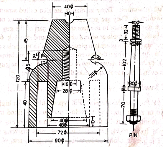
PIN INSULATOR
AIM:
Design and draw the half sectional elevation of pin insulator using Auto cad software.
PROCEDURE:
The following general commands are used to draw the half sectional elevation of pin insulator diagram using Auto cad.
Step 1: Set the limits of the drawing screen.
Step 2: Put ORTHO ON where as necessasary .
Step 3: Using OSNAP function.
Step 4: Draw conductors of appropriate dimension using LINE Command
Step 5: Draw circle of appropriate dimension using circle command.
Step 6: Draw arc using arc command.
Step 7: Use mirror command.
Step 8: Use Hatch command.
Step 9: Use trim command.
Step 10: Use copy command.
Step 11: command: q Save.
RESULT:
The half sectional elevation of pin insulator is drawn by using AutoCAD software.
PIN INSULATOR
EXPERIMENT :3
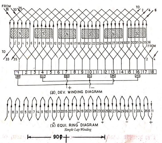
DC LAP WINDING
AIM:
Design and draw a developed DC lap winding diagram for a DC Machine having 6 poles, 36 armature conductors for a single turn coil using Auto cad software.
PROCEDURE:
The following general commands are used to draw the developed DC lap winding diagram using Auto cad.
Step 1: Set the limits of the drawing screen.
Step 2: PUT ORTHOON where ever necessary.
Step 3: Using OSNAP function.
Step 4: Draw conductors of appropriate dimension using LINE Command
Step 5: Use rectangular Array Command for making rows and columns of conductors
Step 6: Use p-line command for making arrows.
Step 7: Use Rectangular command for making poles.
Step 8: Make the numbers on the conductors using TEXT Command.
Step 9: Use Copy, Hatch, Donut, Arc Commands.
Step 10: Command: – q Save.
RESULT:
The DC Lap winding is drawn by using AutoCAD software.
DC LAP WINDING
EXPERIMENT :4
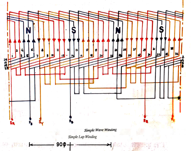
DC WAVE WINDING
AIM:
Design and draw a developed DC simple wave winding diagram for a DC Machine having 4 poles, 34 armature conductors using Auto cad software.
PROCEDURE:
The following general commands are used to draw the developed DC lap winding diagram using Auto cad.
Step 1: Set the limits of the drawing screen.
Step 2: PUT ORTHOON where ever necessary.
Step 3: Using OSNAP function.
Step 4: Draw conductors of appropriate dimension using LINE Command
Step 5: Use rectangular Array Command for making rows and columns of conductors
Step 6: Use p-line command for making arrows.
Step 7: Use Rectangular command for making poles.
Step 8: Make the numbers on the conductors using TEXT Command.
Step 9: Use Copy, Hatch, Donut, Arc Commands.
Step 10: Command: – q Save.
RESULT:
The DC wave winding is drawn by using AutoCAD software.
Solution:
yb and yf can be calculated by using the following formulae.
( yb + yf ) / 2 = ( Z ± 2)/P
( yb + yf ) / 2= (34+2)/4 (for progressive winding)
yb = 9 yf = 9

EXPERIMENT :5
UN-BIFURCATED THREE PHASE CONCENTRIC WINDING
AIM:
To draw concentric un- bifurbcated winding diagram with two planes over hang, for a three phase, 48 slots, 8 poles AC armature.
PROCEDURE:
Step 1: Set the limits of the drawing screen.
Step 2: Put ORTHO ON where as necessasary.
Step 3: Using OSNAP function.
Step 4: Draw conductors of appropriate dimension using LINE Command
Step 5: Use rectangular array command for making rows and columns of conductor.
Step 6: Use pline command for making arrows.
Step 7: Make the numbers on the conductors using TEXT command.
Step 8: Use DONOT Command wherever need.
Step 9: Use copy, layer commands.
Step 10: Commands: q save.
RESULT:
Concentric winding un- bifurcated diagram with two plane over hang, for a three phase, 48 slots, 8 poles AC armature is drawn by using AutoCAD software.
Solution:
Slots/pole/phase = 48/(8 x 3) = 2
Thus one pole phase group consists of two slots.
Coil span = pole pitch = slots per pole = 48/8 =6
Angle between consecutive slots = 180o /6 =30o electrical
EXPERIMENT :6
AC MUSH WINDING
AIM:
Draw a Mush winding diagram for a 4 poles, 36 slots 3 phase armature using Auto cad software.
PROCEDURE:
The following general commands are used to draw the developed AC Mush winding diagram using Auto cad software.
Step 1: Set the limits of the drawing screen.
Step 2: Put ORTHO ON where as necessary.
Step 3: Using OSNAP function.
Step 4: Draw conductors of appropriate dimension using LINE Command
Step 5: Use rectangular Array Command for making rows and columns of conductors
Step 6: Use p-line command for making arrows.
Step 7: Make the numbers on the conductors using TEXT Command.
Step 8: Use Copy, layer Commands.
Step 9: Command: – q Save.
RESULT:
The developed AC mush winding diagram for 4 pole 36 slots 3 phase armature is drawn by using AutoCAD software.
AC MUSH WINDING
EXPERIMENT :7
AC LAP WINDING
Design and draw a developed winding diagram of a double layer Lap winding for a three phase, 6 poles, 18 slots machine. Assume that the winding is full pitched.
PROCEDURE:
The following general commands are used to draw the developed AC lap winding diagram using Auto cad.
Step 1: Set the limits of the drawing screen.
Step 2: PUT ORTHO ON where ever necessary.
Step 3: Using OSNAP function.
Step 4: Draw conductors of appropriate dimension using LINE Command
Step 5: Use rectangular Array Command for making rows and columns of conductors
Step 6: Use p-line command for making arrows.
Step 7: Use Rectangular command for making poles.
Step 8: Make the numbers on the conductors using TEXT Command.
Step 9: Use Copy, Hatch, Donut, Arc Commands.
Step 10: Command: – q Save.
RESULT:
The AC Lap winding is drawn by using AutoCAD software.
Solution:
Slots/pole/phase (spp)= 18/(6 x 3) = 1 slot
For full pitched coils, coil span= pole pitch =18/6=3 slots.
Top coil side 1 in slot 1 is connected to bottom coil side 8 in slot 4. Top coil side 3 in slot 2 is connected to bottom coil side 10 in slot 5 and so on.
Pole pitch corresponding to 180o electrical
Here, the no of slots in one pole pitch=3 slots
Thus one pole phase group consists of two slots.
Angle between consecutive slots = 180o /3 =60o electrical
We know that the phase one displaced by 120o electrical
No of slots by which the phase are displaced= 120o/60o = 2 slots
EXPERIMENT :8
DOL STARTER
AIM:
Draw the line diagram of DOL Starter using Auto cad software.
PROCEDURE:
Step 1: Set the limits of the drawing screen.
Step 2: Put ORTHO ON where as necessasary.
Step 3: Using OSNAP function.
Step 4: Draw line of appropriate dimension using LINE Command
Step 5: Draw circle of appropriate dimension using circle command.
Step 6: Use offset command.
Step 7: Use copy command.
Step 8: Use trim command.
Step 9: command:- q Save.
RESULT:
The line diagram of DOL Starter is drawn by using AutoCAD software.
EXPERIMENT :9
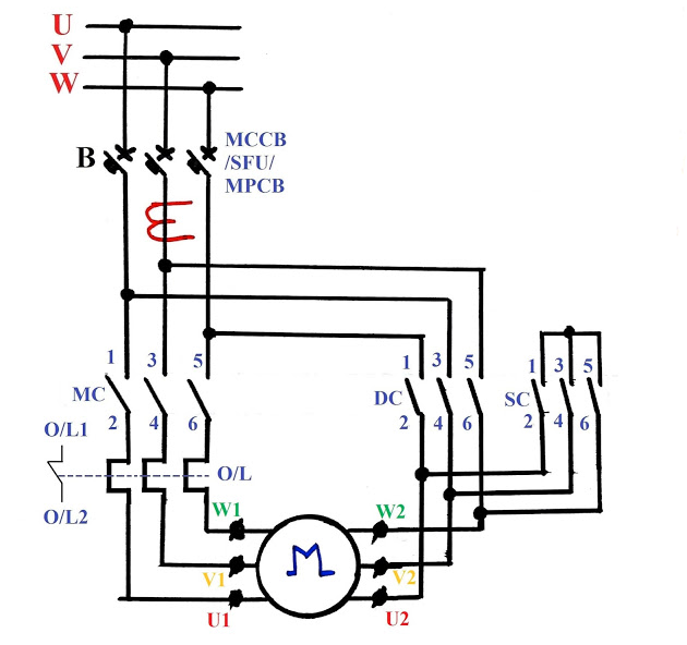
AUTOMATIC STAR DELTA STARTER
AIM:
To draw the line diagram of fully automatic star delta Starter using Auto cad software.
PROCEDURE:
Step 1: Set the limits of the drawing screen.
Step 2: Put ORTHO ON where as necessasary.
Step 3: Using OSNAP function.
Step 4: Draw line of appropriate dimension using LINE Command
Step 5: Draw circle of appropriate dimension using circle command.
Step 6: Use offset command.
Step 7: Use copy command.
Step 8: Use trim command.
Step 9: command:- q Save.
RESULT:
The line diagram of fully automatic star delta Starter is drawn by using Auto cad software.
AUTOMATIC STAR DELTA STARTER


Recent Comments