
Electrical Measurements Notes
1-Theory and classification of measuring instruments.
1. Classify measuring instruments? (2/6 mark)
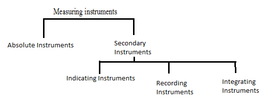
Absolute Instruments : These instruments give the value of quantity to be measured interms of deflection and instrument constants . ex: Tangent Galvanometer
Secondary Instruments : These instruments give directly the value of quantity to be measured by the amount of deflection which is pre-calibrated by camparison with absolute instruments.
Indicating instruments: These instruments indicate the value of voltage, current, power etc. directly on a graduated dial. Ex: Ammeter, voltmeter, Wattmeter…
Integrating instruments : These instruments measures the total amount, either th quantity of electricity or the electric energy supplied to a circuit over a period of time. Ex: Enrgy meter, Ampere hour meter
Recording instruments : These instruments register the quantity to be measured in a given time, and are providd with a pen which moves over graph paper. Ex: Recording voltmeter.
2. List out two examples of integrating instruments?(2)
Enrgy meter, Ampere hour meter, Watt hour meter
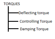
3. List out necessary torques of an indicating instruments? 2
4. State functions of controlling torque? 2
- The force is control the movement of the moving system and to ensure that the magnitude of the deflection of the pointer is always same for the value of quanitity to be measured.
- Controlling force is always opposite to the deflecting torque
- It brings the the pointer to zero position when the instrument disconnected from supply.
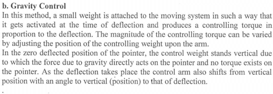
5. Explain different methods of controlling force in instruments? (6)
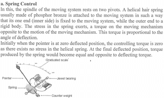
6. List two characteristics of phosphor bronze material used as spring control system? 2
- non magnetic material
- Least weight and inertia
- Low specific resistance material
7. With neat diagram explain damping torque produced in a PMMC instrument? 8
Damping force is necessary to bring the moving system to rest in its final deflected position quickly.
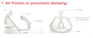
In air friction damping, thin metal vane V is attached to the spindle S, and the vane is made to move inside a sector shaped air chamber while the pointer moves on the graduated scale. The air inside th air chamber opposes the movement of the vane/piston, and thereby the damping force is created.
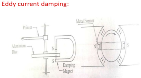
In this method a copper or aluminium disc D is attached to the spindle. When the pointer moves the disc also moves. The disc is made to move in the air gap between the poles of a permanent magnet M. the moving disc cuts the flux, thereby inducing eddy currents in the disc. According to Lenz’s law, the flux produced by the eddy current opposes the movements of the disc, thereby effecting the damping force.
Fluid friction Damping :
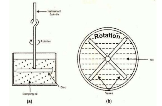
This form is damping is similar to air friction damping. The action is the same as in the air friction damping. Mineral oil is used in place of air and as the viscosity of oil is greater, the damping force is also much greater. The vane attached to the spindle is arranged to move in the damping oil. It is rarely used in commercial type instruments.This instrument only used in vertical positions.
In Fig. (a) a disc attached to the moving system is immersed in the fluid (damping oil).When the moving system moves the disc moves in oil and a frictional drag is produced. For minimizing the surface tension affect, the suspension stem of the disc should be cylindrical and of small diameter.
In the arrangement of Fig. (b) a number of vanes are attached to the spindle. These vanes are submerged in oil and moves in a vertical plane. This arrangement provides greater damping torque.
8. List out two advantages of PMMC instruments over MI instruments ? 2
- Uniform scale
- High efficiency as it requires very little power for its operation
- Very accurate and reliable.
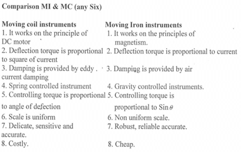
*9. Differentiate PMMC instrument with MI instrument? 6
10. List out advantages and disadvantages of PMMC instrumnts? (6)
Advantags:
- Uniform scale
- High efficiency as it requires very little power for its operation
- Very accurate and reliable.
Disadvantages:
- Cannot used for AC measurements
- More expensive
- Errors are caused due to variations.
11. With neat diagram explain and working principle of PMMC Instruments?
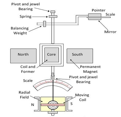
These instruments only used for DC measurements.
Principle : The working of the PMMC instrument is based on the principl that when a current carrying conductor is placed in a magnetic field, it is acted upon by a force which tends to move the conductor. the DC motor also work on this principle.
Construction : It consists of a permanent magnet (ALNICO) and a rectangular coil wound with a very fine gauge insulated copper wire on a thin light aluminium former. Aluminium produces eddy current for damping. Coil and former attached with spindle on either side and supported by jewelled bearings so as to make freely move in the air gap. The pointer is attached to one of the spindles, and it moves on graduated scale when the coil is deflected by the quantity to b measured.
Operation: When the current is passed through the coil, the coil experiences a force due to the interaction of the magnetic fluxes, produced by the permanent magnet and the current in the moving system.
F = BILN Newton (b=flux density, L= length, I= current , N= no of turns)
Torque T = Force x perpndicular distance = BILNr Newton meters.
12. With neat sketch explain constructional details of MI attraction type instruments?
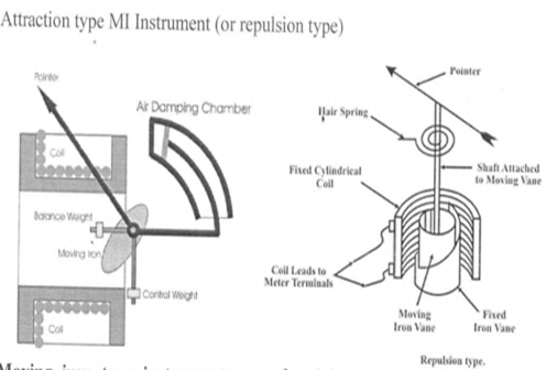
Attraction type:
It works on the principle of magnetic attraction betwween two adjascent pieces of soft iron magnetised by the same magnetic field.
Construction: This instrument consists of an electromagnetic coil have an air core and front of the air core an oval shaped soft iron piece is eccentrically pivotd in a spindle. The spindle is free to move with the help of jewelled bearings, and the pointer is attached to the spindle.
Working : when the electromagnetic coil is connected to the supply,the magnetic field created in the coil is attracts the soft iron piece.Due to the eccentricity of the iron piece, nlarged portion pulled toards the coil. This in turn moves the spindle and make pointer deflcts. The amount of deflection of the pointer is greater when the magnetic field is greater.
2-Measurement of Power and Energy.
1.State the working principle of dynamo meter type instrument?(2)
This instruments works on the principle of DC motor,ie,Whenever a current carrying conductor is kept in a magnetic field, mechanical force exists between the current carrying conductors. the magnetic field is produced by an electro magnet named as fixed coil and the moving coil either connected in series or parallel with the fixed coil carries a propotionate current.
2.Explain the working principle of dynamo meter type wattmeter with neat diagram?
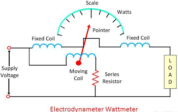
Principle:This instruments works on the principle of DC motor,ie,Whenever a current carrying conductor is kept in a magnetic field, mechanical force exists between the current carrying conductors. it used for measurement of ac as well as dc supply.
Construction: the magnetic field is produced by an electro magnet named as fixed coils(current coil) are connected in series with the load and carry the load current I1. and the moving coil(potential coil) is connected across the load through a series resistor parallel with the fixed coil carries a propotionate cu and carries a current I2 propotional to the load voltage.A pointer is attached the moving coil. air friction damping is used.spring control is used to serve the additional purpose of leading current into and out of the moving coil.
Working : When the wattmeter is connected to the circuit, the current coil carries the load current and pressure coil carries the current propotional to load voltage.due to currents in the coils, mechanical force exists between them.the result is that movable coil moves the pointer over the scale. the pointer comes to rest at a position where deflecting torque equal to controlling torque.reversal of current reverses the both current coil and pressure coil, so used both ac as well as dc power measurement.
2.State the advantage and disadvantages of disadvantages of dynamo meter type instruments?(6)
Advantages: 1, these instruments used for bot AC and DC measurements. 2,These instruments are free from both hysteresis and eddy current losses(air cored coils are used) 3,it can be used to measure power to great accuracy.
Disadvantages: 1, Has low sensitivity 2,The torque is produced is small 3,more expensive than PMMC instruments 4,screening is required to avoid stray fields(because of air core used)
3.Discuss the common errors occurs in measuring instruments.(6)
1,Observational errors : Reading errors caused by looking at the indicator(pointer) from an angle(parallax error).
2,Instrumevntal errors: this error will occur as a result of care;less assembly, damage, false adjustment or when used in false positions.
3, Enviornmental errors : caused by effect of enviornment such as humidity, temperature, vibrations…..
4, Ageing :
5,Frictional errors : They are due to mechanical frictional forces acting at the pivot.they are minimized by using light weight construction of moving system.
6, Switching errors : it caused by the influence of the electrical quantity being measured, through incorrect method of connection before measurement.
4.Discuss the common errors occurs in dynamometer type wattmeter instruments.(6)
- Error due to potential circuit connection:
- Error due to potential coil inductance : Potential coil inductance leads the current lags behind the voltage, the power factor tends to lagging and gives high meter reading.
- Error due to capacitance in potential coil circuits : Potential coil capacitance increase the power factor of the instruments and lading errors in reading.
- Error due to eddy currents : eddy current inducing in the coil by its own magnetic field, the field effect the main current flow through the coil and leading errors.
- Error due to stray magnetic fields: The stray magnetic fields disturbs the main magnetic field leads to error.
- Temperature error : The variation in temperature changes the resistance of the pressure coil and leads to error.
5.Explain the construction & working of single phase induction type energy meter?
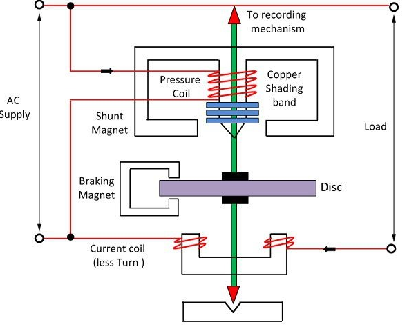
Single phase induction energy meter or watt hour meter are used for the measurement af energy in the ac circuits. it is essentially an induction wattmeter with control spring and pointer removed but break magnet and counting mechanism provided
Constuction: 1: it consists of two electromagnet namely series magnet and shunt magnet, series magnet is wound with heavy wire of few turns connected in series with the load and carries current is propotional to load current called current coils.it is non inductive in nature. shunt magnet is wound with fine wire of many turns called pressure coil connected aacross the supply and highly inductive nature. 2: A thin aluminium disc mount on the spindle is placed between the shunt and series magnet so that it cuts the fluxes of both magnet,. 3: The brake magnet consists of C shaped piece of alloy of steel bent to form a complete magnetic circuit near the rotating disc, throgh a small air gap. Eddy currents induced in the disc produce a braking torque that is propotional to the disc speed.
Theory : When induction watthour meter or energy metrer is connected in the circuit to measure energy, the shunt magnet carries a current propotional to the supply voltage and the series magnet carries the load current. ie, for the driving torque is the same as for induction wattmeter. Driving torque α power , The breaking torque is due to the eddy current produced in the aluminium discs. magnitude off eddy current is propotional to the speed of the disc.
Meter constant = No of revolutions / kWh
Hence the number of revolutions made by a disc for 1kWh of energy consumption is called the meter constant.
6.Explain in detail the reasons for the creeping error and its remedies?
The disc in the watt meter sometimes makes slow but continous rotation at no load ie, when potential coil is excited but with no current flowing in the load. This is called creeping. it may cause due to over compensation of friction, excessive supply voltage, vibration, stray magntic field etc…
In order to prevent the creeping, two diametrically opposite holes are drilled in the disc.
3.Measurement of resistance, inductance and capacitance
1, Name any two methods of finding low resistance?
Ammeter voltmeter method, Potentiometer method
2, Any two method to locate cable fault?
Murray loop test, Varley loop test, Fall of potential test
3, With neat sketch explain wheatstone’s bridge principle?
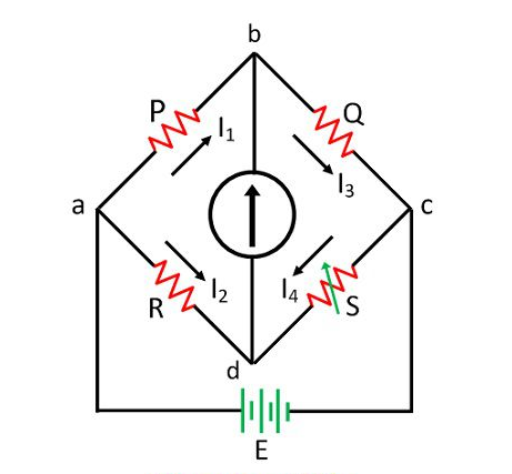
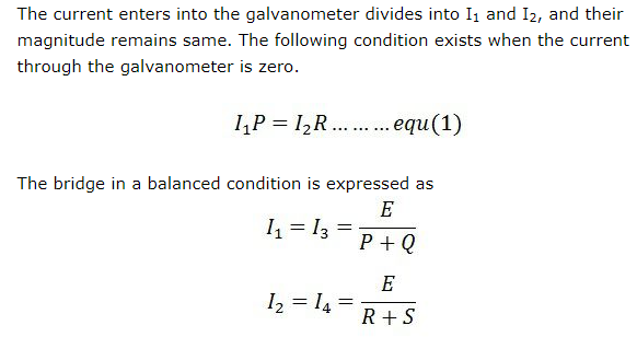
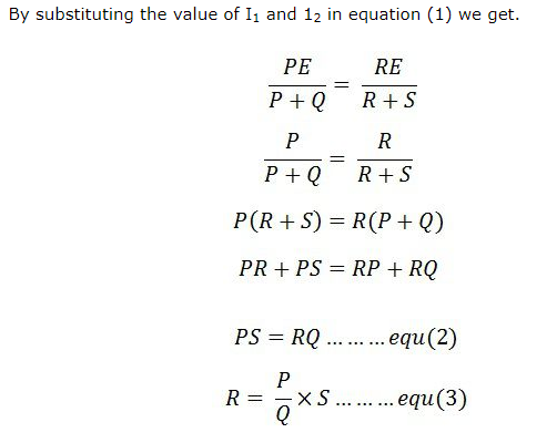
The bridge is in balance condition when no current flows through the coil or the potential difference across the galvanometer is zero. This condition occurs when the potential difference across the a to b and a to d are equal, and the potential differences across the b to c and c to d remain same.
4,Explain the working of vibrating reed type frequency meter?
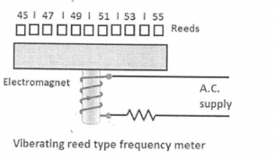
When the electromagnet is connected across the supply whose frequency is to be determined, the bar is attracted twice per cycle as the current reaches its positive and negative peaks. Thus the bar makes two vibrations for each cycle of the alternating current through the electromagnet. since the reeds are attached to the bar, they also tend to vibrate accordingly. but the reed whose natural frequency is exactly double the frequency will vibrate the maximum amplitude due to mechanical resonance. Thus by noting which reed vibrates, we can read the frequency of the supply from the scale.
5.With neat sketch, explain the procedure steps of measurement of earth resistance
by using earth megger?
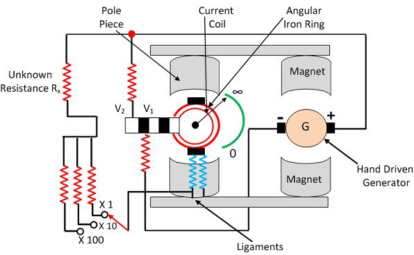
Meggar is the instrument uses for measuring the resistance of the insulation. it works on the basic principle of comparison. the resistance of the insulation is compared with the known value of resistance.
Construction : The construction of the Megger is shown in the figure below. The Megger has one current coil and the two voltage coils V1 and V2. The voltage coil V1 is passed over the magnet connected to the generator. When the pointer of the PMMC instrument deflects towards infinity, it means that the voltage coil remains in the weak magnetic field and thus experienced the very little torque
Working : The Megger has three coils two pressure coils and one current coil. The pressure coil rotates the moving coil in the anticlockwise direction, whereas the current coil rotates it in the clockwise direction.When the unknown resistance is connected in the circuit, the pointer of the moving coil becomes stable. The pressure coil and the current coil balance the pointer and set it in the middle of the scale.The deflection of the pointer is directly proportional to the voltage applied to the external circuit.
6. With neat sketch explain Maxwell’s inductance bridge?
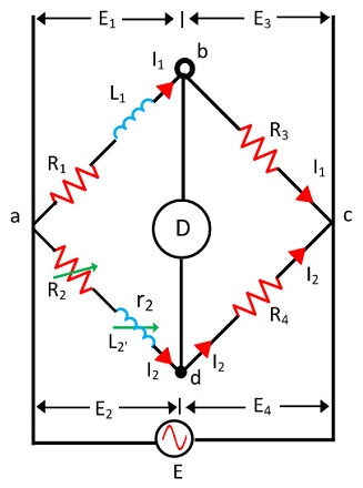
In the above circuit, L1 = Unknown inductance having resistance R1
R2 = Variable resistance R3 and R4 = Known resistance
As we know that, for a balanced bridge the multiplication of impedances of opposite arms must be equal.
Impedance of arm ab, Z1 = (R1+jwL1)
Impedance of arm cd, Z2 = R4
Impedance of arm ad, Z3 = (R2+r2+jwL2)
Impedance of arm bc, Z4 = R3
Hence for balanced bridge, Z1Z2 =Z3Z4
(R1+jwL1)xR4 = (R2+r2+jwL2)xR3
R1R4-R2R3-r2R3+jw(L1R4-L2R3) = 0
Equating real and imaginary part we get,
R1R4-R2R3-r2R3 = 0 ……………(1)
and (L1R4-L2R3) = 0 ……………(2)
From (1), R1R4 = R2R3+r2R3 = R3(R2+r2)
Hence, R1 = (R3/R4)(R2+r2)
Now from (2), L1R4 = L2R3
Hence, L1 = L2R3 / R4
Thus unknown inductance L1 and its resistance R1 may be calculated.
7. With neat sketch explain Schering’s bridge?
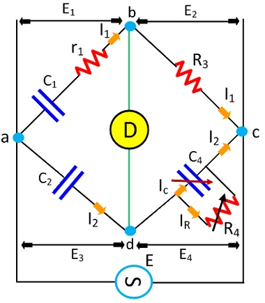
refer text
4.Special purpose measuring instruments
1. List any two functions of CRO?
1. Measurement of voltages, frequencies, waveforms
2. In radio work, finding BH curves for hysteresis loop
2.Draw the block diagram of CRO?
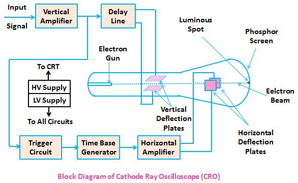
The cathode-ray oscilloscope (CRO) is a common laboratory instrument that provides accurate time and amplitude measurements of voltage signals over a wide range of frequencies. Its reliability, stability, and ease of operation makes it suitable as a general purpose laboratory instrument.
A general purpose oscilloscope consists of the following parts:
- Cathode ray tube
- Vertical amplifier
- Delay line
- Time base generator
- Horizontal amplifier
- Trigger circuit
- Power supply
Cathode Ray Tube – It is the heart of the oscilloscope. When the electrons emitted by the electron gun strikes the phosphor screen, a visual signal is displayed on the CRT.
Vertical Amplifier – The input signals are amplified by the vertical amplifier. Usually, the vertical amplifier is a wide band amplifier which passes the entire band of frequencies.
Delay Line – As the name suggests, this circuit is used to delay the signal for a period of time in the vertical section of CRT. The input signal is not applied directly to the vertical plates because the part of the signal gets lost, when the delay time is not used. Therefore, the input signal is delayed by a period of time.
Time Base (Sweep) Generator – Time base circuit uses a uni-junction transistor, which is used to produce the sweep. The saw tooth voltage produced by the time base circuit is required to deflect the beam in the horizontal section. The spot is deflected by the saw tooth voltage at a constant time dependent rate.
Horizontal Amplifier – The saw tooth voltage produced by the time base circuit is amplified by the horizontal amplifier before it is applied to horizontal deflection plates.
Trigger Circuit – The signals which are used to activate the trigger circuit are converted to trigger pulses for the precision sweep operation whose amplitude is uniform. Hence input signal and the sweep frequency can be synchronized.
Power supply – The voltages required by CRT, horizontal amplifier, and vertical amplifier are provided by the power supply block. It is classified into two types –
(1) Negative high voltage supply 2) Positive low voltage supply
3. Differentiate analog and digital meters?
| Analoge meters | digital meters |
| Analog signal is continous signal which represents physical measurements | digital signals are discrete time signals generated by digital modulation |
| Waves are denoted by sine waves | square waes |
| only uses analog devices | computing and digital electronics |
| memory stored in the form of wave signal | form of digital bits |
| low cost and potable | high cost & not easy portable |
| low impedence | high impedence |
| large power consumption | low power usage |


Recent Comments