
Half Wave Rectifier Circuits Lab Manual
Half wave rectifier circuits
Aim:
To study the characteristics of Half wave rectifier with and without filter and calculate its ripple factor
Components and equipments required:
- Diode 1N4007 1no
- Resistor 1K 1no
- Step down transformer 6-0-6 1no
- Breadboard, CRO, BNC probe, connecting wires etc….
Theory:
Rectifier is a circuit used to convert AC to DC The diode conducts only when its anode is at a higher voltage with respect to cathode.
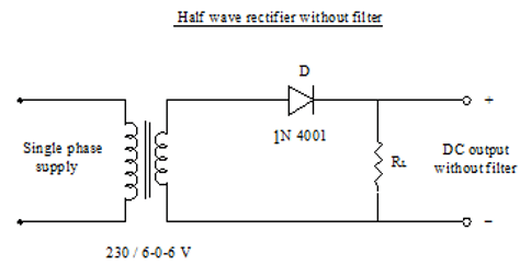
- Half wave circuit consist of an ac voltage source, step down transformer, a single pn junction diode and load.
- In a half wave rectifier circuit, during positive half cycle of the input, the diode gets forward biased and conducts. The current flows through the load resistance RL and voltage is developed across if. During negative half cycle of the input, the diode gets reverse biased and the flow of current will be blocked.
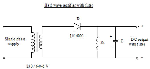
- The main function of a filter circuit is to minimize the ripple content in the rectifier output. Certain electronic circuits need smooth DC voltage.
- Thus a pure AC is converted to unidirectional signal. The main function of a filter circuit is to minimize the ripple content in the rectifier output. Certain electronic circuits need smooth DC voltage. A filter circuit does this function. In this circuit, a suitable single capacitor C is connected across the rectifier and in parallel with the load RL to achieve the filter section.
- Vdc = Vm/Π = 0.318 Vm
- Vrms = 0.5 Vm
- Form factor =rms value/average value = 0.5 Im/0.318 Im = 1.57
- PIV (Peak inverse voltage) =Vm
- Ripple factor = 1.21
- Efficiency = 40.6 %
Procedure:
- Wire the half wave rectifier circuit without capacitor after testing all components.
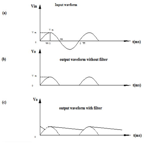
- Switch On mains supply. Observe the transformer secondary voltage waveform and output voltage waveform across the load resistor, simultaneously on the CRO screen. Note down the peak values.
- Calculate the ripple factor using the expression.
- Connect the capacitor filter and observe the waveforms. Note down V1 and V2 and calculate the ripple factor using the expression.
Circuit Diagram
Wave Form


Recent Comments