
Rectifiers
Rectifiers:
Rectifier is defined as a electronic circuit which employs one or more diodes to converting ac voltage into unidirectional pulsating voltage. A Rectifier utilizes PN Junction diode. During positive half cycle of ac input, the diode is forward biased and conducts current. During negative half cycle of ac input, the diode is reversed biased and conducts no current.
They are classified as :
- Half Wave Rectifier.
- Full Wave Rectifier.
- Centre tapped full Wave rectifier.
- Bridge full Wave rectifier.
Half Wave Rectifier:
Rectifier is a circuit used to convert AC to DC The diode conducts only when its anode is at a higher voltage with respect to cathode.
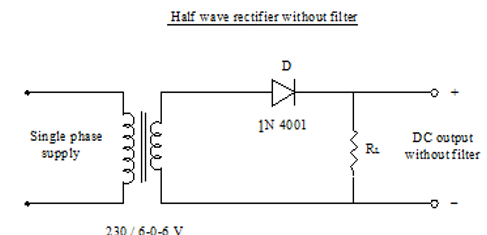
- Half wave circuit consist of an ac voltage source, step down transformer, a single pn junction diode and load.
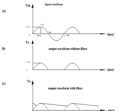
- In a half wave rectifier circuit, during positive half cycle of the input, the diode gets forward biased and conducts. The current flows through the load resistance RL and voltage is developed across if. During negative half cycle of the input, the diode gets reverse biased and the flow of current will be blocked. there is no current flow.
- The output is not a steady dc but only a pulsating dc wave. To eliminate the dc components in the output, by using filter circuit.
- The main function of a filter circuit is to minimize the ripple content in the rectifier output. Certain electronic circuits need smooth DC voltage.
- Vdc = Vm/Π = 0.318 Vm
- Vrms = 0.5 Vm
- Form factor =rms value/average value = 0.5 Im/0.318 Im = 1.57
- PIV (Peak inverse voltage) =Vm
- Ripple factor = 1.21
- Efficiency = 40.6 %


Recent Comments