
HOPKINSON’S TEST
HOPKINSON’S TEST
AIM:
- To conduct Hopkinton’s test on a pair of identical DC machines to pre-determine the efficiency of the machine as generator and as motor and to plot the efficiency curve.
APPARATOUS REQUIRED:
| S.No. | Apparatus | Range | Type | Quantity |
| 1 | Ammeter | |||
| 2 | Voltmeter | |||
| 3 | Rheostats | |||
| 4 | SPST Switch | |||
| 5 | Tachometer |
MACHINES DETAILS:
THEORY :
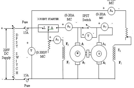
This test is called regenerative test or back to back test which can be carried out on two identical d.c. machines mechanically coupled to each other. Thus the full load test can be carried out on two identical shunt machines without wasting their outputs. One of the machines is made to act as a motor while the other as a generator. The mechanical output obtained from the motor drives the generator. Electrical output from the generator supplies part of input to the motor. The motor is connected to the supply mains only to compensate for losses .In the absence of losses, the motor-generator set would have run without any external power supply. But due to losses, the generator output is not sufficient to drive the motor. Thus motor takes current from the supply to account for losses.
The switch S is kept open.The first machine connected to supply will act as motor. Thus second machinewhich is acting as generator will act as a load to the first machine. The speed of motor is adjusted to normal value with the help of the field rheostat. The voltmeter reading is observed. The voltage of the generator is adjusted by its field rheostat so that voltmeter reading is zero. This will indicate that the generator voltage is having same magnitude and polarity of that of supply voltage. This will prevent heavy circulating current flowing in the local loop of armatures on closing the switch. Now switch S is closed. The two machines can be put into any load by adjusting their field rheostats. The generator current I2 can be adjusted to any value by increasing the excitation of generator or by reducing the excitation of motor. The various reading shown by different ammeters are noted for further calculations.
The input to the motor is nothing but the output of the generator and small power taken from supply. The mechanical output given by motor after supplying losses will in turn drive the generator.
PRECAUTIONS:
- The field rheostat of the motor should be in the minimum position at the time of starting and stopping the machine.
- The field rheostat of the generator should be in the maximum position at the time of starting and stopping the machine.
- SPST switch should be kept open at the time of starting and stopping the machine.
PROCEDURE:
- Connections are made as per the circuit diagram.
- After checking the minimum position of field rheostat of motor, maximum position of field rheostat of generator, opening of SPST switch, DPST switch is closed and starting resistance is gradually removed.
- The motor is brought to its rated speed by adjusting the field rheostat of the motor.
- The voltmeter V1 is made to read zero by adjusting field rheostat of generator and SPST switch is closed.
- By adjusting field rheostats of motor and generator, various Ammeter readings, voltmeter readings are noted. (Care should be taken to avoid current exceeding rated values of motor and generator)
- The rheostats and SPST switch are brought to their original positions and DPST switch is opened
CIRCUIT DIAGRAM
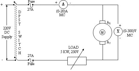
DETERMINATION OF ARMATURE RESISTANCE
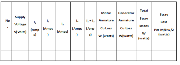
TABULAR COLUMN:
As Motor
| sl.no. | V (volt) | I1 (A) | I2(A) | I3(A) | Motor armature copper loss | Field loss | stray losses/2W) | Total Losses (W) | Out put power | Input power | efficiency |
AS Generator
| sl.no. | V (volt) | I1(A) | I2(A) | I3(A) | Motor armature copper loss | Field loss | stray losses/2W) | Total Losses (W) | Out put power | Input power | efficiency |


Recent Comments