
Load Test Slip Ring Induction Motor
LOAD TEST ON 3-PHASE SLIP RING INDUCTION MOTOR
AIM:
To obtain following performance characteristics,
- Line current, torque, power factor,
- efficiency, speed and slip Vs output.
- Torque Vs slip.
APPARATOUS REQUIRED:
| S.No. | Apparatus | Range | Type | Quantity |
| 1 | Ammeter | |||
| 2 | Voltmeter | |||
| 3 | Rheostats | |||
| 4 | SPST Switch | |||
| 5 | Tachometer |
MACHINES DETAILS:
THEORY :
The slip ring induction motor has two separate parts, one is the stator and other is the rotor. The stator consists of a three phase winding. When 3 phase supply is given to the stator it produce a rotating magnetic field. The speed with which the magnetic field rotate is called synchronous speed.
synchronous speed Ns =120 f / P
Rotor consists of star connected 3 phase winding. The three terminals of the star connected rotor are connected to three slip rings. These slip rings are used to connect external resistance to rotor circuit.
When three phase supply is given to the stator, a rotating magnetic field rotating at synchronous speed is produced. This rotating magnetic field induced an emf and hence current in the stator winding.when current flows through the rotor winding a torque is produced in the rotor conductors ( current carrying conductor placed in a magnetic field it will experience a torque) due to this torque the rotor starts rotating. Rotor accelerates in the direction of rotation of magnetic field reducing the relative speed between the magnetic field of stator and rotor.
If the motor attains synchronous speed the rotor will not be cutting the magnetic flux and torque induced will be zero. Practically doesnot achieve synchronous speed. The difference between synchronous speed and rotor speed is indicated using slip.
Percentage slip ;s = NS-N/NS *100
PRECAUTIONS:
- TPST switch is kept open initially.
- The external resistance in the rotor circuit should be kept at max. value.
PROCEDURE:
- Connections are given as per circuit diagram.
- After observing precautions motor is started on no load.
- As speed increases, the external resistance is gradually cut out.
- The no-load readings are taken.
- If watt meter reads negative, interchange its current coils terminals
- The meter readings are then noted for various load conditions.
CIRCUIT DIAGRAM

TABULAR COLUMN:
| SL. NO | LOAD CURRENT (A) | LOAD VOLTAGE (V) | W1 | W2 | INPUT POWER (W) W1+W2 | SPEED (N) | SPRING BALANCE READING (Kg) | TORQUE (Nm) | OUTPUT POWER (w) | EFFICIENCY | SLIP | POWER FACTOR |
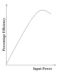
SAMPLE GRAPH :


Recent Comments