
OC and SC Test on Three Phase Transformer
OC & SC TEST ON THREE PHASE TRANSFORMER
AIM:
- To determine the per phase equivalent circuit parameter referred to LV side & HV side.
- To predetermine the efficiency & regulation for different load condition and to plot the curves.
APPARATOUS REQUIRED:
| S.No. | Apparatus | Range | Type | Quantity |
| 1 | Ammeter | |||
| 2 | Voltmeter | |||
| 3 | Rheostats | |||
| 4 | SPST Switch | |||
| 5 | Tachometer |
MACHINES DETAILS:
THEORY :
A three-phase transformer can be constructed by having three primary and three Secondary wingdings on a common magnetic circuit. The three single-phase core type transformers, each with windings (primary and secondary) on only one leg Have their unwound legs combined to provide a path for the returning flux. The Primaries as well as secondaries may be connected in star or delta. If the primary is energized from a 3-phase supply, the central limb (i.e., unwound limb) carries the fluxes produced by the 3-phase primary winding. Since the Since the phasor sum of three primary currents at any instant is zero, the sum of three fluxes passing through the central limb must be zero. Hence no flux exists in the central limb and it may, therefore, be eliminated. This modification gives a three leg core type 3-phase transformer. In this case, any two legs will act as a return path for the flux in the third leg. For example, if flux is f in one leg at some instant, then flux is f/2 in the opposite direction through the other two legs at the same instant. All the connections of a 3-phase transformer are made inside the case and for delta-connected winding three leads are brought out while for star connected winding four leads are brought out.
PRECAUTIONS:
PROCEDURE:
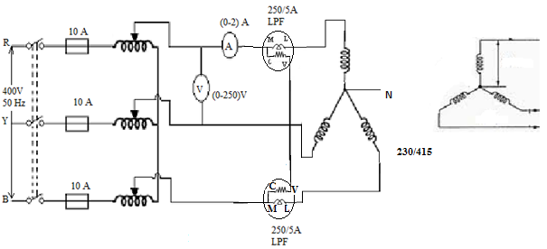
OC TEST :
- Connections are made as per the circuit diagram.
- Three phase auto transformer is placed in minimum position & supply is given by DPST switch is closed and starting resistance is gradually removed.
- Adjust the auto transformer to get the rated voltage which is read by voltmeter which is equal to 230V.
- Note the readings, sum of of the readings of two wattmeter’s to give core loss.
- set the auto transformer to its initial position & switch off the supply.
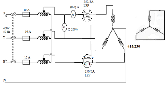
SC TEST:
- Connections are made as per the circuit diagram.
- Three phase auto transformer is placed in minimum position & supply is given by DPST switch is closed and starting resistance is gradually removed.
- Adjust the auto transformer to get the rated current which is read by Ammeter in high voltage side which is equal to rated current.
- Note the readings, sum of of the readings of two wattmeter’s to give copper loss.
- set the auto transformer to its initial position & switch off the supply.
CIRCUIT DIAGRAM
OC TEST
SC TEST
TABULAR COLUMN:
OC TEST
| V0 (volt) | I0 (Ampere) | W0(watt) |
SC TEST
| Vsc (volt) | Isc(Ampere) | Wsc(watt) |


Recent Comments