
Sumpner’s Test on a Single Phase Transformer
SUMPNER’S TEST ON A PAIR OF 1-Ф TRANSFORMER
AIM:
To conduct OC & SC tests on the given 1- Transformer and to calculate its
- Equivalent circuit parameters
- Referred to H.V side
- Referred to L.V side
- Efficiency at various loads.
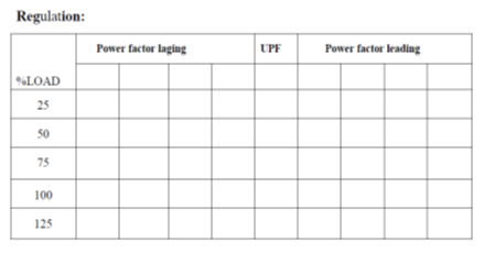
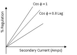
- Regulation at various power factors 4) Maximum Efficiency.
APPARATOUS REQUIRED:
| S.No. | Apparatus | Range | Type | Quantity |
| 1 | Ammeter | |||
| 2 | Voltmeter | |||
| 3 | Rheostats | |||
| 4 | SPST Switch | |||
| 5 | Tachometer |
MACHINES DETAILS:
THEORY :
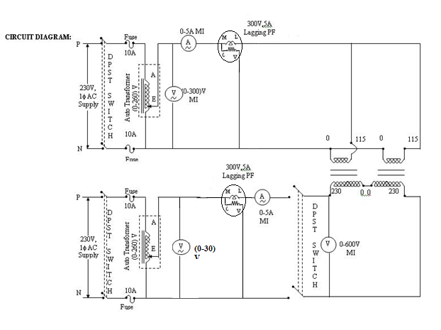
In this test load test is conducted without actual loading. Sumpner’s test which can only be conducted simultaneously on two identical transformers. In conducting the Sumner’s test the primaries of the two transformers are connected in parallel across the rated voltage supply (V1), while the two secondary’s are connected in phase opposition. As per the superposition theorem, if V2 source is assumed shorted, the two transformers appear in open circuit to source V1 as their secondary are in phase opposition and therefore no current can flow in them. The current drawn from source V1 is thus 2I0 (twice the no-load current of each transformer) and power is 2P0 (= 2P0) twice the core loss of each transformer). When V1 is regarded as shorted, the transformers are series-connected across V2 and are short-circuited on the side of primaries. Therefore, the impedance seen at V2 is 2Z and when V2 is adjusted to circulate full-load current (Ifl), the power fed in is 2Pc (twice the full-load copper-loss of each transformer). Thus in the Sumpner’s test while the transformers are not supplying any load,full iron-loss occurs in their core and full copper-loss occurs in their windings; net power input to the transformers being (2Po+2Pc).The heat run test could , therefore, be conducted on the two transformers, while only losses are supplied.
PRECAUTIONS:
PROCEDURE:
- Connections are done as per the circuit diagram.
- By using the variac rated voltage is made to apply across the low voltage side of the transformer.
- Before closing the DPST switch the reading of the voltmeter connected across DPST switch must be zero.
- By using the variac in H.V side rated current is made to flow in the circuit.
- At this instant note down all the meter readings.
- By using above tabulated readings the efficiency and regulation of the transformers are calculated.
CIRCUIT DIAGRAM
TABULAR COLUMN:
SAMPLE GRAPH :


Recent Comments