
Load Characteristics of DC Shunt Generator
LOAD CHARACTERISTICS OF DC SHUNT GENERATOR
AIM:
To obtain internal and external characteristics of DC shunt generator.
APPARATUS REQUIRED:
| S.No. | Apparatus | Specification | Quantity |
| 1 | Ammeter | ||
| 2 | Voltmeter | ||
| 3 | Rheostats | ||
| 4 | Loading Rheostat | ||
| 5 | Tachometer |
MACHINES DETAILS:
THEORY:
In a shunt generator, the field winding is connected in parallel with the armature winding so that terminal voltage of the generator is applied across it.The shunt field winding has many turns of fine wire having high resistance. Therefore, only a part of armature current flows through shunt field winding and the rest flows through the load.
For a DC Shunt GeneratorE0=V + IaRa
Ia= IL + Ish
Ish= V/Rsh
Where, E0 is the induced emf
V is the terminal voltage
Ia is the armature current
IL is the load current
Internal characteristics: it is the plot of the induced voltage E with armature current. Drop in voltage is due to armature reaction which increases with increase in load current.
External characteristics: It is the plot of terminal voltage with load current at constant field resistance and speed. As the load on the machine is varied the terminal voltage drops it is due to
- The drop in voltage across the armature resistance, IaRa drop.
- Armature reaction the air gap flux decreases which will reduced the induced emf.
- The drop in terminal voltage due to 1 & 2 results in decrease field current which further reduces the induced emf.
PRECAUTIONS:
- The field rheostat of motor should be at minimum position.
- The field rheostat of generator should be at maximum position.
- No load should be connected to generator at the time of starting and stopping.
PROCEDURE:
- Connections are made as per the circuit diagram.
- After checking minimum position of DC shunt motor field rheostat and maximum position of DC shunt generator field rheostat, DPST switch is closed and starting resistance is gradually removed.
- Adjust the motor field rheostat to adjust the speed to rated speed of generator.
- Under no load condition, Ammeter and Voltmeter readings are noted, after bringing the voltage to rated voltage by adjusting the field rheostat of generator.
- Load is varied gradually until rated current and for each load, voltmeter and ammeter readings are noted.
- Then the generator is unloaded and the field rheostat of DC shunt generator is brought to maximum position and the field rheostat of DC shunt motor to minimum position, DPST switch is opened.
FORMULAE:
Eg = V + Ia Ra (Volts)
Ia = IL + If (Amps)
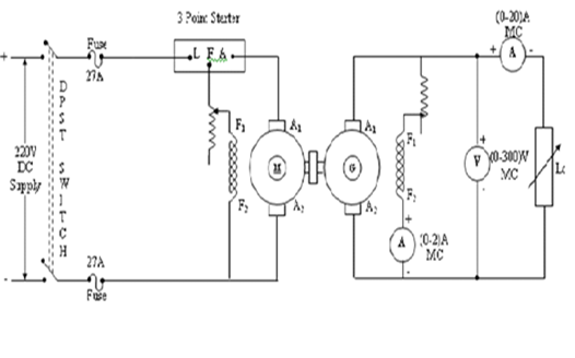
CIRCUIT DIAGRAM:
PROCEDURE TO FIND Ra:
- Connections are made as per the circuit diagram.
- Supply is given by closing the DPST switch.
- Readings of Ammeter and Voltmeter are noted.
- Armature resistance in Ohms is calculated as Ra = (Vx1.5) /I
TABULAR COLUMN:
| S.No. | Voltage V (Volts) | Current I (Amps) | Armature Resistance Ra (Ohms) |
| S.No. | Field Current If (Amps) | Load Current IL (Amps) | Terminal Voltage (V) Volts | Ia = IL + If (Amps) | Eg=V + Ia Ra (Volts) |
SAMPLE GRAPH:
RESULT:


Recent Comments