
Open Circuit Characteristics of Dc Shunt Generator
OPEN CIRCUIT CHARACTERISTICS OF DC SHUNT GENERATOR
AIM:
- To plot the OCC of a given DC Generator at rated speed & to find the critical speed & critical resistance.
- To plot the OCC at 3/4 th rated speed.
- To find the value of additional resistance to be added in field circuit in order to make it as critical field resistance.
APPARATOUS REQUIRED:
| S.No. | Apparatus | Range | Type | Quantity |
| 1 | Ammeter | |||
| 2 | Voltmeter | |||
| 3 | Rheostats | |||
| 4 | SPST Switch | |||
| 5 | Tachometer |
MACHINES DETAILS:
THEORY :
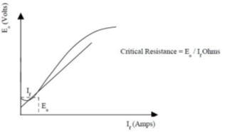
The open circuit characteristic gives the variation of generated voltage(E) with field current (If) at a constant speed.
E=ZɸN/60. P/A
ie, E α ɸN
When speed is constant, generated voltage is proportional to field flux. When the field current is zero,a small residual flux is present in the machine and a small voltage is generated even when field current is zero. As the field current is increased the voltage increases linearly with field current. At some values of If, magnetic circuit starts getting saturated. In saturation region, voltage increases only slightly with increase in field current. So the generated voltage is directly proportional to speed.
OCC of a generator shows the relation between the no load generated emfin the generator & the field current in armature. If when the generator is driven at constant rated speed, the field current is varied by adjusting the resistance connected in the field. The field current is increased in suitable steps starting from zero and the corresponding value of induced emf, E0is noted. The curve does not start from the origin but from the point above the Y-axis, slightly above the origin. This is due to the residual magnetism in the poles of generator at low value of field current.
If we are given O.C.C. of a generator at a constant speed N1, then we can easily
draw the O.C.C. at any other constant speed N2.
PRECAUTIONS:
- The field rheostat of motor should be in minimum resistance position at the time of starting and stopping the machine.
- The field rheostat of generator should be in maximum resistance position at the time of starting and stopping the machine.
- SPST switch is kept open during starting and stopping.
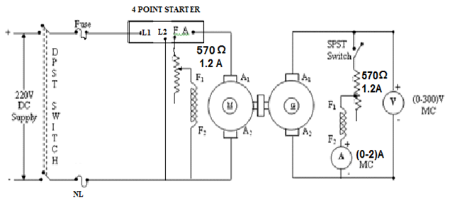
PROCEDURE:
- Connections are made as per the circuit diagram.
- After checking minimum position of motor field rheostat, maximum position of generator field rheostat, DPST switch is closed and starting resistance is gradually removed.
- By adjusting the field rheostat, the motor is brought to rated speed.
- Voltmeter and ammeter readings are taken when the SPST switch is kept open.
- After closing the SPST switch, by varying the generator field rheostat, voltmeter and ammeter readings are taken.
- Field current is varied till generated voltage reaches 125% of the rated voltage.
- After bringing the generator rheostat to maximum position, field rheostat of motor to minimum position, SPST switch is opened and DPST switch is opened.
CIRCUIT DIAGRAM
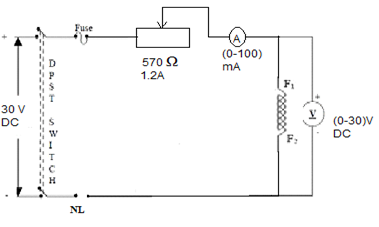
CIRCUIT FOR MEASURING FIELD RESISTANCE
TABULAR COLUMN:
| Sl No. | Field Current If (Amps) | Armature Voltage Eo (Volts) | |
Measuring field Resistance
| Sl No. | Ammeter reading(A) | Voltmeter reading(v) | |
SAMPLE GRAPH :
RESULT:


Recent Comments