
Load Test on Dc Shunt Motor
LOAD TEST ON DC SHUNT MOTOR
AIM:
- To conduct load test on DC shunt motor and to determine the efficiency using mechanical loading arrangement
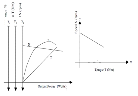
- To Draw the following characteristics curves
- Torque Vs Armature current (electrical characteristics)
- Speed Vs Armature current
- Speed Vs Torque (Mechanical characteristics)
- Performance curve
APPARATUS REQUIRED:
| Sl no | Name of Apparatus | Type | Specification | Qty |
| 1 | Ammeter | |||
| 2 | Voltmeter | |||
| 3 | Rheostat | |||
| 4 | Tachometer |
MACHINES DETAILS:
THEORY:
Ina shunt motor the field winding is connected in parallel with the armature .The field current and the armature current are not same. Shunt field windings are having large number of turns of wire having high resistance. So shunt field current is relatively small compared with the armature current. Applied voltage andRsh of a shunt motor are constant, so field current Ish also will be constant.
Ish=V/Rsh
Hence, the flux in a shunt motor is constant.
N α Eb/ɸ
As ɸ is constant, speed of shunt motor will be constant.
Taα ɸ Ia
ɸ is constant, so Taα Ia
Sostarting torque of a shunt motor islow.
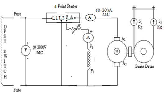
The load test is conducted by applying a spring balance load to brake drum of machine. By tightening the belt over the pulley different load can be applied. The spring balance reading S1 and S2 are noted and the effective radius ‘r’ of the pulley is measured.
If N is the speed of motor, then Torque developed T= (S1-S2)rgNm
The output power can be calculated as 2πNT/60 Watts
Efficiency of the motor=output power/input power.
PRECAUTIONS:
- DC shunt motor should be started and stopped under no load condition.
- Field rheostat should be kept in the minimum position.
- Brake drum should be cooled with water when it is under load.
PROCEDURE:
- Connections are made as per the circuit diagram
- After checking the no load condition and minimum field rheostat position starter resistance is gradually removed.
- The motor is brought to its rated speed by adjusting the field rheostat.
- Ammeter, Voltmeter readings, speed and spring balance readings are noted under no load condition.
- The load is then added to the motor gradually and for each load, voltmeter, ammeter, spring balance readings and speed of the motor are noted(Take readings up to rated current of the machine).
- The motor is then brought to no load condition and field rheostat to minimum position,then switch off the supply.
FORMULAE USED:
- Torque (T) = 9.81 (S1-S2). r
Where, S1, S2→ Spring balance readings in kg
r→ Radius of brake drum in m
9.81→Constant to convert kg to Newton
2. Output Power (Pout)= 2πNT/60
Where N= Speed in rpm
3. In put power (Pin) = VL.IL Watts
VL=Input voltage in volts
IL=Input current in Amps
4. % Efficiency =( Pout/Pin)*100
CIRCUIT DIAGRAM:
TABULAR COLUMN:
| S. No. | Input Voltage VL (Volts) | In put current IL (amps) | Speed N(rpm) | Spring balance Readings S1 , S2 , S1-S2 | Torque T(Nm) | Output Power Pout (Watts) | Input Power Pin (watts) | % η |
SAMPLE GRAPH:
RESULT:


Recent Comments