
Load Test on Single Phase Transformer
LOAD TEST ON SINGLE PHASE TRANSFORMER
AIM:
To perform load test on 1-phase transformer and determine the following:
- Efficiency at different loads and to plot efficiency vs. load curve.
- Regulation of the transformer and to plot regulation vs. load curve.
APPARATOUS REQUIRED:
| S.No. | Apparatus | Range | Type | Quantity |
| 1 | Ammeter | |||
| 2 | Voltmeter | |||
| 3 | Rheostats | |||
| 4 | SPST Switch | |||
| 5 | Tachometer |
MACHINES DETAILS:
THEORY :
The transformer is a device which transfers energy from one electrical circuit to another electrical circuit through magnetic field as coupling medium. In this process it does not change the frequency of voltage or current. It works on the basic principle of electromagnetic induction (mutually induced e. m. f.). Being a static device it has a very high efficiency as compared to rotating machine of same rating as the losses are less.
When primary winding of transformer is energized with source of voltage V1 an e.m.f. E2 is induced across the secondary winding and it is also equal to secondary terminal voltage V2 till there is no load across secondary winding. As soon as load is applied across the secondary winding the terminal voltage is decreased from E2 to V2 this phenomenon of changing the voltage is called “voltage regulation”.
We can define voltage regulation in numerical term as “it is change in secondary terminal voltage from no load to full load with respect to the secondary no load voltage”.
The voltage regulation should be as small as possible. Transformer being highly inductive device works on lagging power factor unless the load of highly capacitive nature is connected across the secondary winding to make overall circuit resistive purely or capacitive in nature
PRECAUTIONS:
- Instruments used should be of proper range.
- All the connections should be tight.
- The parallax error should not be there.
- Give constants supply through the auto Transformer.
- Never touch live conductors or Terminals.
PROCEDURE:
- Make the connections as per the circuit diagram.
- Keep the switch S on secondary side open so that load is zero to measure no load voltage. Also keep knob of auto transformer at zero output voltage position.
- Now increase the voltage through auto transformer until voltage in voltmeter V2 reads rated value of secondary winding & read no load voltage E2.
- Switch on certain lamps in the lamp in the bank load such that secondary winding current be approximately 10% of the rated current of secondary side.
- Take the readings from Wattmeter W2, Voltmeter V2, & Ammeter I2.
- Increase the load current in steps of 10% of the rated value by switching on few more lamps & take the readings of the Wattmeter, Ammeter & Voltmeter till it reaches 120-1255 of rated value.
- Reduce the load to zero by switching of the lamps one-by-one.
- Switch off the AC-Supply.
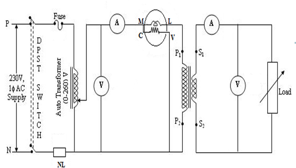
CIRCUIT DIAGRAM
TABULAR COLUMN:
| Sl. No. | W1 (Watts) | E2 (volts) | V2 (Volts) | I2(Amp) | (Watts) | ||


Recent Comments