
No Load and Blocked Rotor Test on Squirrel Cage Induction Motor
NO LOAD AND BLOCKED ROTOR TEST ON 3 PHASE SQUIRREL CAGE INDUCTION MOTOR.
AIM:
- To determine the equivalent circuit parameters.
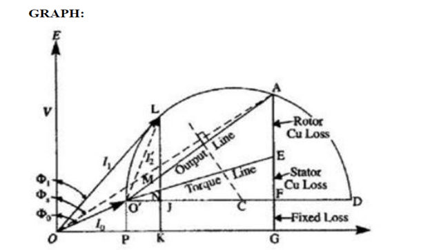
- To draw the performance characteristics using data obtained from the circle Diagram.
APPARATOUS REQUIRED:
| S.No. | Apparatus | Range | Type | Quantity |
| 1 | Ammeter | |||
| 2 | Voltmeter | |||
| 3 | Rheostats | |||
| 4 | SPST Switch | |||
| 5 | Tachometer |
MACHINES DETAILS:
THEORY :
A 3-phase induction motor consists of stator, rotor & other associated parts. In the stator, a 3- phase winding (provided) are displaced in space by 120. A3- phase current is fed to the winding so that a resultant rotating magnetic flux is generated. The rotor starts rotating due to the induction effect produced due the relative velocity between the rotor winding & the rotating flux.
No load test:-
If the motor is run at rated voltage and frequency without any mechanical load, it will draw power necessary to supply the no load losses. The no load current will have two components. The active component and the magnetizing component, the former being very small as the no load losses are small. The power factor at no load is therefore very low. The no load power factor is always less than 0.5 and hence at no load one of the wattmeter at input side reads negative. The no load input W0 to the stator consists of
- Small stator copper loss
- Core losses
- The loss due to friction and windage.
The rotor copper loss can be neglected, since slip is small at no load.
Blocked rotor test :-
The stator is supplied with a low voltage of rated frequency just sufficient to circulate rated current through the stator with the rotor blocked and short circuited. The power input, current and the voltage applied are noted down. The power input during the blocked rotor test is wholly consumed in the stator and rotor copper losses. The core loss is low because the applied voltage is only a small percentage of the normal voltage. Again since the rotor is at stand still the mechanical losses are absent. Hence the blocked rotor input can be taken as approximately equal to the copper losses.
PRECAUTIONS:
- The motor field rheostat should be kept in the minimum resistance position.
- The alternator field potential divider should be kept in the minimum voltage position.
- Initially all switches are in open position.
PROCEDURE:
PROCEDURE FOR NO LOAD TEST:-
- Connections are made as shown in the diagram for no load test.
- Brake drum is made free to rotate by loosening the belt.
- The auto transformer is placed in zero position. Then the supply is switched on and the auto transformer is adjusted to supply small voltage to the machine. Initially current will rise to high value. Wait until the current reaches to low current. Then increase the voltage to rated value.
- Readings of the two wattmeter, voltmeter and ammeter are noted and tabulated.
- If the wattmeter reads negative, interchange current coil terminals and take wattmeter reading as negative.
- Switch off supply.
PROCEDURE FOR BLOCKED ROTOR TEST :-
- Connections are made as shown in the diagram for blocked rotor test.
- The rotor is blocked by tightening the belt on the brake drum.
- The auto transformer is set to the zero voltage position.
- Then the three phase supply is switched on.
- By adjusting the auto transformer, the ammeter reading is made equal to rated current of the machine.
- Readings of the two wattmeter, voltmeter and the ammeter are noted and tabulated.
- If the wattmeter reads negative, interchange current coil terminals and take wattmeter reading as negative.Switch off supply.
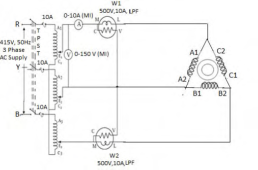
CIRCUIT DIAGRAM
FOR NO LOAD:-
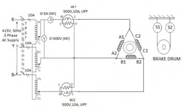
FOR BLOCKED ROTOR
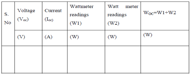
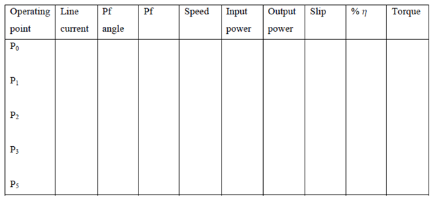
TABULAR COLUMN:
NO LOAD TEST:-
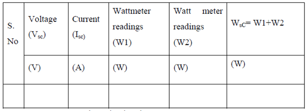
BLOCKED ROTOR TEST:-
SAMPLE GRAPH


Recent Comments