
Slip Test on Salient Pole Alternator
SLIP TEST ON SALIENT POLE ALTERNATOR
AIM:
- To determine Xd and Xq by conducting slip test.
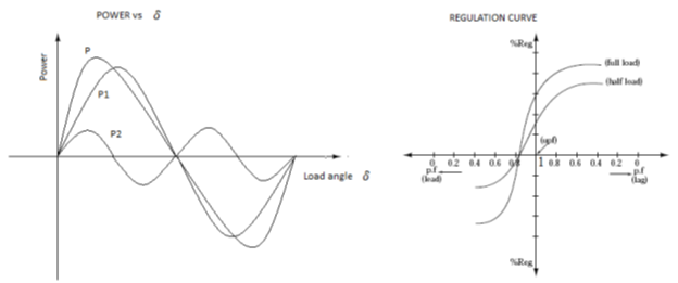
- To pre-determine the regulation at upf different power factor and load.
- To plot power Vs load angle graph.
APPARATOUS REQUIRED:
| S.No. | Apparatus | Range | Type | Quantity |
| 1 | Ammeter | |||
| 2 | Voltmeter | |||
| 3 | Rheostats | |||
| 4 | SPST Switch | |||
| 5 | Tachometer |
MACHINES DETAILS:
THEORY :
If a synchronous machine runs at a slightly less than the synchronous speed, the field structure is exposed to the rotating mmf of armature reaction. Hence the poles and armature reaction mmf fall in phase and out of phase at slip frequency. Where the axis of two coincides, the armature acts through the field magnetic circuit, including maximum voltage in the field. The direct axis reactance Xd (and hence the impedance Zd) is maximum resulting in the armature current being minimum. Where the field poles are in quadrature with armature mmf, quadrature axis reactance Xq (and hence the impedance Zq) will be minimum resulting in the armature current maximum. Hence,
Zd = Max. voltage / min. current
Zq = Min. voltage / max. current
PRECAUTIONS:
- TPST switch is kept open initially.
- The external resistance in the rotor circuit should be kept at max. value.
PROCEDURE:
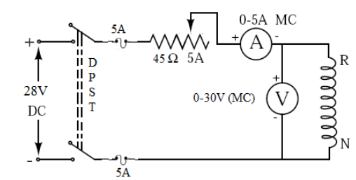
- Make connections as shown in circuit diagram.
- Start the set and bring it to near synchronous speed keeping the field of the alternator open.
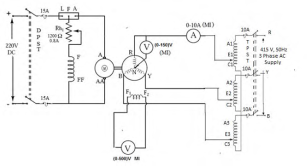
- Apply an AC voltage of reduced magnitude (about 25% of the rated value). The field poles and armature mmf should rotate in same direction this can be verified by measuring the voltage across the field winding (It should be nearly equal to zero) Otherwise interchange the stator terminals.
- Adjust the speed of the alternator to get sufficient oscillations (Maximum deflection) in the meter.
- Note down the maximum and minimum value of ammeter and voltmeter.
CIRCUIT DIAGRAM
TABULAR COLUMN:

SAMPLE GRAPH :


Recent Comments