
Fuses & Circuit Breakers
FUSES
A fuse is a safety device, used for the purpose of protecting a circuit against excess current (overload/short circuit condition).It is a short piece of metal inserted in series with the circuit, which melts when excessive current flows through it and thus breaks the circuit.
Characteristics of Fuse element
- Low melting point ( like tin & lead)
- High conductivity (like silver & copper)
- Free from deterioration due to oxidation ( silver..)
- Low cost (eg: lead, tin, copper..)
Inverse Current Characteristics of a Fuse
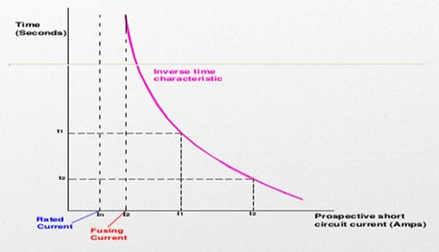
The fuse has inverse time current characteristics ie, if the short circuit current is high, time taken to interrupt is low and vice versa happens when the fault current is low. Time required to blow out the fuse depends upon the magnitude of fault current (short circuit / over loaded) . The greater the current, smaller the time taken by the fuse to blow out.
General terms
i) Fuse element /Fuse Wire: It is that part of the fuse which melts when an excessive current flows in the circuit, and thus isolates the device from the supply mains.
ii) Current rating of fuse element: It is the maximum current that can pass continuously without over heating or melting.
iii) Fusing Current: It is the minimum current at which the fuse element melts & thus disconnects the circuit protected by it.
iv) Fusing Factor: It is the ratio of minimum fusing current to the current rating of fuse element.
Fusing factor = Fusing current / current rating of fuse element
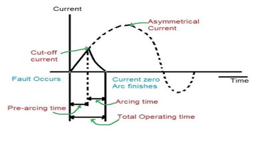
i) Cut off current : The maximum value of the fault current actually reached before the fuse melts is called cut off current.
ii) Pre-arcing time : This is the time between the commencement of the fault current and the instant that the arc is initiated.
When a fault occurs the fault current rises rapidly and generates heat in the fuse element. As the fault current reaches the cut off value, the fuse element melts and an arc is initiated. The time from the start of the fault current to the instant of the arc is initiated is known as pre-arcing time.it is generally small value.(0.001 second)
iii) Arcing time: This the time between the end of pre arcing time and the instant, when the circuit is open (arc is extinguished) & the current becomes permenantly zero.
iv)Total operating time: It is the sum of pre arcing time and arcing time.v) Breaking capacity: This is the RMS value of ac component of maximum prospective current that a fuse can deal with at rated service voltage
Types of fuses
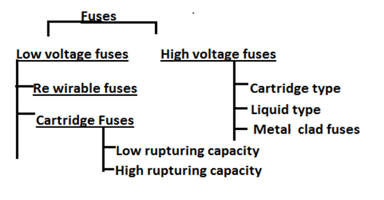
Rewirable fuse:
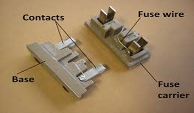
Semi closed type rewirable fuse also known as kit-kat type. Is used where low value of fault current are to be interrupted. It consists of a fuse base & fuse carrier. Fuse Base of made by porcelain and carries the fixed contacts to which the incoming and out going phase wires are connected. The fuse carrier also of porcelain and holds the fuse element(tinned copper/ alloy of tin & lead)
When a fault occurs, the fuse element is blown out and the circuit is interrupted. The fuse carrier is taken out and replace the fuse element & reinserted.
- Simple construction & low initial and renewal cost.
- Fuse elements are alloy of tin and lead, tinned copper wire….
- Deterioration of the fuse element by oxidation due to heating. ( due to oxidation through the continuous heating up of the element & reduction in cross sectional area leading increasing resistanca, ie. The current rating of the fuse element is decreased. The fuse operates at lower current than originally rated ie, premature rupturing.
- Low breaking capacity & lack of discrimination.
- Possibility of renewal by the fuse wire of wrong size or by improper material.
- Semi closed type fuses are made upto 500A.
- Used only for domestic and lighting loads.
HRC FUSE
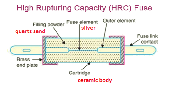
Construction :
- It is the one of the simplest form of low voltage fuse & adopted for distribution purposes.
- They are cylindrical in shape, and are made of heat resisting Ceramic material.
- Fuse element are enclosed in a air tight vaccum chamber, deterioration does not take place. Normally silver alloy used as fuse element.
- They have metal end caps (Brass ): they are fixed element between which is attached the fuse element. (Brass: Alloy of copper & zinc, high tensile strength & high resistant to corrosion )
- Outer space of fuse element within the body is filled with filling powder or quartz sand or silica ….(for quench the arcing quickly without any hazards and act as a cooling medium)
Working :
- Under normal load condition: the fuse element is at a temperature below its melting point. Ie, it carries the normal current without over heating.
- Faulted condition : When a fault occurs ,the current increases and the fuse element melts before the fault current reaches its first peak. The heat produced in the process vaporizes the melted silver element.
- The chemical reaction between the silver vapour and the filling powder results in the formation of a high resistance substance forms like globules which helps in quenching the arc and cooling without making spark or gas.
Advantages:
- They are capable of clearing high as well as low fault current.
- They do not deteriorate with oxidation & age.
- They have high speed of operation.
- They have inverse current time characteristics.
- They require no maintenance, ie, they are cheaper than other circuit interrupting devices.
- No external flame, ie. safety of operation is very good.
- Fusing factor is 1.1
- They provide reliable discrimination.
Disadvantages:
- They have to be replaced after each operation.
- Heat produced by the arc may affect the associated switches.
- It produces over heating of adjascent switches.
Selection of HRC Fuses
- The normal current of the circuit.
- The extent which the over current protection is needed.
- The circuit voltage available across the fuse after its operation as it should not be more than the rated voltage of the fuse.
- The rupturing capacity of the fuse should not be less than the current to be broken.
- The extent of discrimination needed when it is used along with other fuses.
Circuit breaker
A circuit breaker is a mechanical switching device, which can open or close a circuit under normal as well as fault condition. Which can,
1) make or break a circuit either manually or by remote control under normal conditions.
2) break a circuit automatically under fault condition.
3) make a circuit either manually or remote control under fault conditions.
Construction
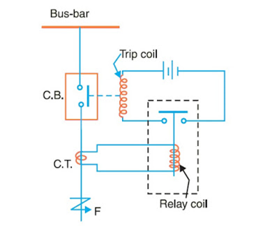
- Mainly it consists of a fixed contact and movable sliding contact, called electrodes following a relay circuit and tripping circuit
- Relay circuit for detects the faults and supplies information to the breaker for circuit interruption.It consists of a Current transformer :and a tripping circuit.
- Current transformer : primary winding of CT is connected in series with the circuit to be protected and secondary of CT connected the relay operating movable contact.
- Tripping coil : It contains a source of supply, trip coil of circuit breaker and relay stationary contacts.
Working
Under Normal condition : The emf of the secondary winding of a Current transformer is small, and the current flowing in the relay operating coil is insufficient to close the relay contacts. This keep the trip coil of the circuit breaker unenergized. ie, the circuit breaker movable contacts is in closed position under normal conditions.
Faulted Condition: When a fault occurs, a large current flows through the primary winding of CT, This increase the secondary emf & hence the current through the relay operating coil. The relay contacts are closed and the trip coil of the breaker is energized to open the contacts of the circuit breaker.
When the contacts of the CB are operated under fault condition, an arc is struck between them. Thus the current is able to continue until the discharge ceases. The production of arc not only delays the current interruption but also generates enormous heat which may cause damage the system. Ie, main problem in a CB is extinguish the arc within the shortest possible time so that heat generated by it may not reach a dangerous value.
Arc Phenomenon
When a short circuit occurs. A heavy current flows through the contacts of the CB before they are opened by the protective system. When the contacts begins to separate from the fixed contacts, the contact area decreses rapidly and the large fault current causes increased the current density and hence rise in temperature.
Initiation of arc mainly to methods. 1) Field emission 2) Thermionic emission
The heat produced in the medium (air/oil) between the contacts is sufficient to ionize the air or vapourise and ionize the oil. The ionised air or vapour acts as conductor and an arc is struck between the contacts. The arc provides a low resistance path and the current in the circuit remains uninterrupted so long as the arc persists.
During the arcing period, the current flowing between the contacts depends upon the arc resistance. The greater the arc resistance, the smaller the current flows between the contacts.
The arc resistance depends upon the following factors,
1)Degree of ionization
2)Length of the arc(separation of contacts)
3)Cross section of arc
Methods of Arc extinction
There are two methods of extinguishing the arc in circuit breakers …
1.High Resistance Method
2.Low Resistance Method / Zero current method
High Resistance Method
- Application: Low voltage / Medium voltage of AC or DC Circuit breakers…(MCB)
- Resistance of the arc is increased rapidly to a high value with time so that current is reduced to a value, such that the voltage of source is no longer enough to maintain the arc voltage and arc is extinguished. The principle disadvantage of this method is enormous energy is dissipated in the arc. So it is used in low capacity DC and AC circuit breakers.
- The resistance of the arc may be increased by,
1)Lengthening the arc
2)Cooling the arc
3)Reducing the cross section of the arc
4)Splitting the arc
Low resistance / zero current method :
- In 50 Hz AC current wave form, natural current zero occurs after every 10msec. At current zero arc has no energy from source. In zero point interruption, plasma quickly removed from the contact space by various techniques.
- Only heat of arc has times constant which results in continuation of arc during next half cycle.
- The dielectric strength of the contact space is built very rapidly after current zero so that arc is extinguished. The rapid increase of dielectric strength of the medium near current zero can be achieved by, a) Causing the ionized particle in the space Between contacts to recombine into neutral molecules. b)sweeping the ionized particles away and replacing them by unionized particle.
Classification of Circuit breakers:
Based on their quenching medium, circuit breakers are classified by,
- Oil circuit breakers
- Air blast circuit breakers
- Vaccum circuit breakers
- Sulphur hexa fluoride circuit breakers


Recent Comments