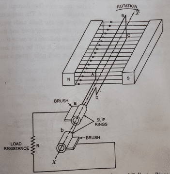
A single turn rectangular copper conductor loop ABCD rotating in clockwise direction about its own axis XX′ in the uniform magnetic field.
The two ends of coils are joined to slip ring ’a’ and ’b’ which are insulated from each other.
Two collecting brushes are used to collect the induced current in the coil to convey it to the external load R.
As the coil is rotated in the magnetic field by some mechanical means, the flux linking with the loop changes continually, therefore, an emf is induced in it.
The magnitude of emf induced at any instant is proportional to the rate of change of linking flux at that instant and its direction is given by Fleming’s right hand rule.
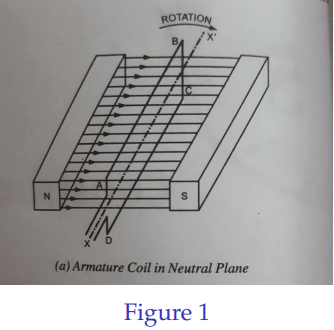
While rotating at the instant the loop ABCD assumes the position shown in Fig. (1) i.e. when the loop ABCD is just parallel to the faces of field magnets N and S, the flux linking with the loop is maximum but the rate of change of linking flux is zero, as at this instant no flux is cut by the coil sides AB and CD which are just moving parallel to them.
Hence induced emf is zero when the loop is in this position. This position of the loop is known as neutral position and let it be taken starting position and angle of rotation be measured from this position.
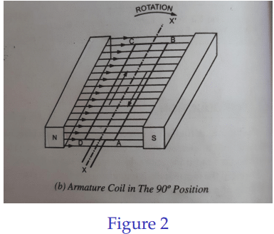
As the coil is turned in clockwise direction at a constant speed, the coil sides begin to cut across the field, slowly at first but at gradually increasing rate. Thus the magnitude of emf induced gradually increases as the loop moves and becomes maximum when the loop assumes the position shown in Fig.(2).
The direction of emf induced in the coil, as given by Fleming’s right hand rule, is from B to A and from D to C.
The coil sides are moving at right angles to the field and are, therefore, cutting across the field at maximum rate, consequently, the emf induced at this instant is of maximum value.
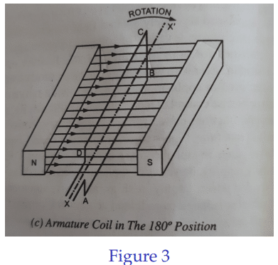
In the next quarter of the revolution of the loop i.e. between 90◦ to 180◦, the rate at which the conductors cut across the magnetic field gradually decreases, causing the magnitude of induced emf to fall gradually with the angular movement of the loop and becomes zero at the instant
The loop becomes again parallel to the faces of the field magnets but with the sides AB and CD′s position interchanged with respect to zero position Fig. (3)
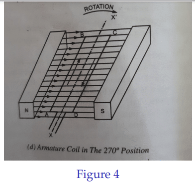
In the third quarter of the revolution of loop i.e. between 180◦ to 270◦ the rate at which the conductors cut across the magnetic field hence induced emf gradually increases as the loop moves and becomes maximum at the instant, the loop assumes the position shown in Fig. (4)
The direction of emf in the loop is now from A to B and from C to D i.e. opposite to that in the first two quarters.
In the fourth quarter of the revolution of the loop i.e. between 270◦ to 360◦, the induced emf decreases as the coil moves and becomes zero when it completes 2π radians or 360◦ from the starting instant.
At this instant the loop comes to its absolute original position and hence the loop is said to have completed one cycle. The cycle then repeats for each revolution of the armature.
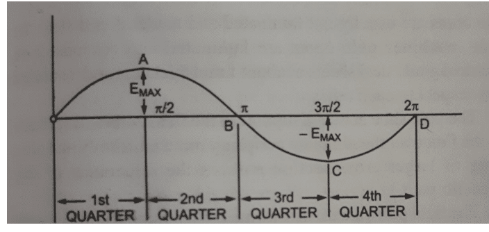
The emf thus generated in the loop is shown in above Fig from which it is obvious that emf induced in armature conductors is of pulsating nature. Such an emf is known as an alternating emf.
The current induced in the coil is collected and conveyed to the external load circuit by connecting the coil terminals to two continuous and insulated rings, known as slip rings or collector rings, mounted on the generator shaft and making the two stationary brushes pressing against the slip rings, one brush bearing on each ring
When the coil is rotated, the generated alternating emf causes a current to flow first in one direction and then in the other through the coil and external circuit. Such a current is called an alternating current
To obtain the unidirectional or direct current – The slip rings are replaced by split ring made of a conducting material and splitted into two halves separated from each other by insulation and brushes are placed diametrically opposite instead of being side by side.


Recent Comments