
No Load and Blocked Rotor Test on Single Phase Induction Motor
NO LOAD AND BLOCKED ROTOR TEST ON SINGLE PHASE INDUCTION MOTOR
AIM:
- To obtain the equivalent circuit parameter of the single phase induction motor.
- To predetermine the line current, power factor, efficiency and the torque developed at 4% slip.
APPARATOUS REQUIRED:
| S.No. | Apparatus | Range | Type | Quantity |
| 1 | Ammeter | |||
| 2 | Voltmeter | |||
| 3 | Rheostats | |||
| 4 | SPST Switch | |||
| 5 | Tachometer |
MACHINES DETAILS:
THEORY :
Single phase motors are similar in construction to poly phase squirrel cage induction motor with exception that the stator has single phase winding. Therefore in single phase motors rotating magnetic field if not produced, but only a pulsating field is produced. The torque is also pulsating and hence single phase motors are not self starting. In order to make them self starting, they are converted to two phase motors at starting. A centrifugal switch is used to cut off the starting winding after motor picks up full speed.
PRECAUTIONS:
- TPST switch is kept open initially.
- The external resistance in the rotor circuit should be kept at max. value.
PROCEDURE:
FOR NO LOAD TEST:-
- Connections are done as shown in the diagram.
- Supply is switched on with dimmer stat in the minimum position.
- A low voltage is applied at starting.
- Gradually as motor picks up speed, the rated voltage is applied.
- The corresponding meter readings are noted.
FOR BLOCKED ROTOR TEST:-
- For this test, starting winding is disconnected.
- A small voltage is applied so that the rated current of the motor flows.
- Corresponding meter readings are noted. (No physical blocking is required since starting windings is not connected).
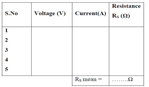
- The resistance of stator winding is also measured.
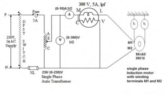
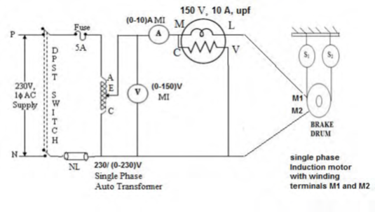
CIRCUIT DIAGRAM
FOR NO LOAD:-
FOR BLOCKED ROTOR:-

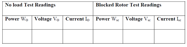
TABULAR COLUMN:


Recent Comments