
V-I Characteristics of SCR
STATIC V-I CHARACTERISTICS OF SCR
AIM:
To plot the static V-I characteristics of the given SCR.
EQUIPMENTS AND COMPONENTS REQUIRED:
| Sl No | Equipment/Component | Specification | Quantity |
| 1 | SCR- | ||
| 2 | Ammeters- | ||
| 3 | Power Supply- | ||
| 4 | Wattage Resistors- | ||
| 5 | Voltmeters- |
THEORY:
A silicon controlled rectifier (SCR) is the oldest and most widely used member of the thyristor family. The SCR is a four layer pn-pn device with three junctions. It has three terminals: anode, cathode and gate. The SCR is used essentially as a controlled switch,. Fast switching action, small size, high reliability, low loss, high current and high voltage ratings are the useful features which make the SCR suitable for power control in many applications.
The static V-I characteristics of an SCR is shown in figure. The SCR has three modes of operation: reverse blocking mode, forward blocking mode (off state) and forward conduction mode (on state).
CIRCUIT DIAGRAM:
OBSERVATIONS:
| VAK (V) | IA (µA) |
Reverse Blocking Mode:
When the cathode is positive with respect to the anode, the junctions J1 and J3 are reverse biased and J2 is forward biased. Only a small leakage current of the order of a few milli-amperes or micro-amperes flows and the device is in the reverse blocking mode. When the voltage is increased to the reverse breakdown voltage, the depletion layers at the junctions J1 and J3 breakdown and the current through the device increases to a high value.The high current at high voltage causes more losses in the device and the junction temperature may exceed the permissible value resulting in the damage of the device.
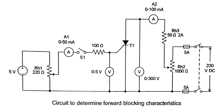
Forward Blocking Mode:
When the anode is made positive with respect to the cathode, J1 and J3 are forward biased and J2 is reverse biased. The reverse biased junction J2 limits the anode current to a few milli-amperes (forward leakage current). The SCR is then said to be in the forward blocking mode. Application of a small positive gate current causes slight increase of forward leakage current.
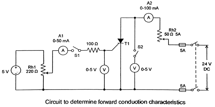
Forward conduction mode:
When the SCR is in the forward blocking mode, if the anode to cathode voltage is increased to the forward breakdown voltage, junction J2 breaks down so that the SCR becomes equivalent to a conducting diode. The voltage across the device falls to a small value and the anode current is limited by the load impedance. When the forward voltage is less than the forward breakdown voltage, the SCR can be triggered into conduction by applying a pulse of positive gate current. Lower anode to cathode voltage requires higher gate trigger current and higher anode to cathode voltage requires lower gate trigger current. If the gate current is sufficiently large, the device can be turned on with a small anode to cathode voltage.
PROCEDURE:
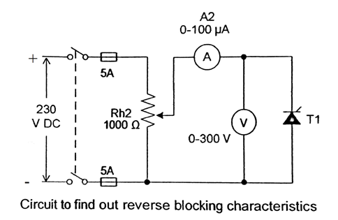
Reverse Blocking Characteristics:
Connections are made as in figure (i). Keeping the potential divider in its minimum position, 230V supply is switched on. The cathode to anode voltage is gradually increased and the ammeter and voltmeter readings are noted.
CIRCUIT DIAGRAM:
Observations:
| Ig = 0 | Ig = 0.5 Igt | ||
| VAK(V) | IA (µA) | VAK(V) | IA (µA) |
CIRCUIT DIAGRAM:
Observations:-
| VAK (V) | IA (A) |


Recent Comments