
Synchronous Induction Motor Lab Manual
SYNCHRONOUS INDUCTION MOTOR
AIM:
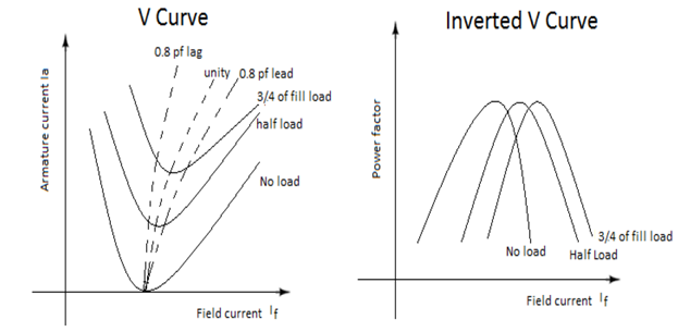
- To draw the V and inverted V curves of a 3 phase Synchronous Motor.
APPARATOUS REQUIRED:
| S.No. | Apparatus | Range | Type | Quantity |
| 1 | Ammeter | |||
| 2 | Voltmeter | |||
| 3 | Rheostats | |||
| 4 | SPST Switch | |||
| 5 | Tachometer |
MACHINES DETAILS:
THEORY :
The variation of field current effects the power factor at which the synchro- nous motor operates. For a syn motor, the armature current phasor is given by Ia=V-E where V is the applied voltage .From the above equation it is clear that the magnitude and phase angle of phasor Ia depends upon the value of DC excitation. When the syn. Motor is operated at constant load with variable field excitation, it is observed that:
- When the excitation is low, the armature current is lag in nature & the magnitude is comparatively high.
- If the excitation is gradually increased, the magnitude of Ia is gradually decreasing and the angle of lag is gradually reduced.
- At one particular excitation, the magnitude of Ia corresponding to that load in minimum and vector will be in phase with V vector.
- If the excitation is further increased, the magnitude of Ia again gradually increased and Ia ,vector goes to leading state and the angle of load is also gradually increased.
PRECAUTIONS:
- TPST switch is kept open initially.
- The external resistance in the rotor circuit should be kept at max. value.
PROCEDURE:
FOR DETERMINATION OF V AND INVERTED V CURVES:
- Connections are given as per the circuit diagram.
- The auto transformer is adjusted such that it reads the rated voltage.
- At no-load condition, the field excitation was varied and the corresponding line current and the wattmeter readings are noted.
- Then by keeping 75% load, the excitation was adjusted by varying the field rheostat and the above readings are noted.
- Same procedure was followed for full load.
FOR LOAD TEST:-
- Connections are given as per the circuit diagram.
- By varying the auto-transformer, rated voltage was kept across the voltmeter.
- At no-load, the line current, the line current, wattmeter readings and the spring balance readings were noted down.
- Then by adding the load in steps, the above said readings were noted.
- The above procedure was followed until it reaches the rated current.
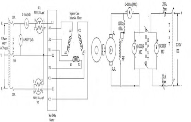
CIRCUIT DIAGRAM
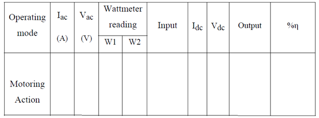
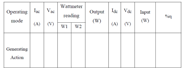
TABULAR COLUMN:
For motor:
For generator:
SAMPLE GRAPH :


Recent Comments