
DC Machines Lab Manual
EXPERIMENT NO : 1
OPEN CIRCUIT CHARACTERISTICS OF SELF EXCITED GENERATOR
AIM:
To conduct open circuit test on a self excited generator and plot the OCC at rated speed and different speed. Determine the critical speed and critical resistance of the machine.
APPARATOUS REQUIRED:
| S.No. | Apparatus | Range | Type | Quantity |
| 1 | Ammeter | |||
| 2 | Voltmeter | |||
| 3 | Rheostats | |||
| 4 | SPST Switch | |||
| 5 | Tachometer | |||
MACHINES DETAILS:
PROCEDURE:
- Connections are made as per the circuit diagram.
- After checking minimum position of motor field rheostat, maximum position of generator field rheostat, start the prime mover by clipping ICDP.
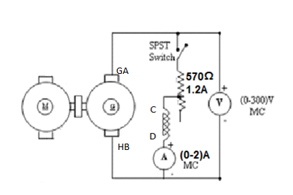
- The machine runs at its rated speed (with the switch open) Note the residual emf on voltmeter. Close the key K and adjust resistance. if the voltmeter reading is increases the connections are correct. Otherwise interchange the connections of the generator field winding terminal C and D.
- Adjust R2 suitably for different values of field current and note the don current and voltage in each step.
- Field current is varied till generated voltage reaches 125% of the rated voltage.
- After bringing the generator rheostat to maximum position, field rheostat of motor to minimum position, SPST switch is opened and DPST switch is opened.
RESULT:
The open circuit test of a self excited generator was conducted and the OCC was plotted at rated speed and off rated speed.
CIRCUIT DIAGRAM
TABULAR COLUMN:
| SL NO. | Field current If In amps | OC terminal voltage | |
| Eo at 1450 rpm | Eo at 1500 rpm | ||
SAMPLE GRAPH :
EXPERIMENT NO : 2
OPEN CIRCUIT CHARACTERISTICS OF SEPERATELY EXCITED GENERATOR
AIM:
To conduct open circuit test on a seperately excited generator and plot the OCC at rated speed and off rated speed. Determine the critical speed and critical resistance of the machine.
APPARATOUS REQUIRED:
| S.No. | Apparatus | Range | Type | Quantity |
| 1 | Ammeter | |||
| 2 | Voltmeter | |||
| 3 | Rheostats | |||
| 4 | SPST Switch | |||
| 5 | Tachometer | |||
MACHINES DETAILS:
PROCEDURE:
- Connections are made as per the circuit diagram.
- After checking minimum position of motor field rheostat, maximum position of generator field rheostat, DPST switch is closed and starting resistance is gradually removed.
- The machine runs at its rated speed (with the switch open) Note the residual emf on voltmeter. Close the key K and adjust resistance. if the voltmeter reading is increases the connections are correct. Otherwise interchange the connections of the generator field winding terminal C and D.
- Adjust R2 suitably for different values of field current and note the down current and voltage in each step.
- Then cut the rheostat gradually in steps and note down the field current and terminal voltage in each step, continue till the Field current is varied till generated voltage reaches 125% of the rated voltage.
- After bringing the generator rheostat to maximum position, field rheostat of motor to minimum position, SPST switch is opened and DPST switch is opened.
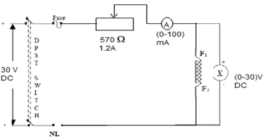
- For finding field resistance, connect the fig 2 as shown in fig. take two or three readings and tabulate it.
RESULT:
The open circuit test of a self excited generator was conducted and the OCC was plotted at rated speed and off rated speed.
CIRCUIT DIAGRAM
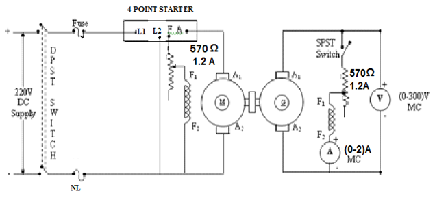
CIRCUIT FOR MEASURING FIELD RESISTANCE
TABULAR COLUMN:
| SL NO. | Field current If In amps | OC terminal voltage | |
| Eo at 1450 rpm | Eo at 1500 rpm | ||
Measuring field Resistance
| Sl No. | Ammeter reading(A) | Voltmeter reading(v) | |
EXPERIMENT NO : 3
SPEED CONTROL OF A DC SHUNT MOTOR BY FIELD CONTROL METHOD (FLUX CONTROL METHOD)
AIM:
To control the sped of a DC shunt motor in field control method and plot the field current Vs speed curve.
APPARATUS REQUIRED:
| Sl no | Name of Apparatus | Type | Specification | Qty |
| 1 | Ammeter | |||
| 2 | Voltmeter | |||
| 3 | Rheostat | |||
| 4 | Tachometer | |||
MACHINES DETAILS:
PROCEDURE:
1. Connections are made as per the circuit diagram
2. keep the field rheostat at minimum position and armature rheostat at maximum position.
3. After checking switch on the supply. Then keep the rheostat in the armature circuit to some fixed value
4. Ammeter, Voltmeter readings, speed and spring balance readings are noted.
5. vary the field rheostat and note the corresponding voltmeter, ammeter readings and speed of the motor are noted. Take a set of readings.
6. change the voltage across the armature by adjusting armature rheostat and repeat the experiment. take another set of readings, Adjust the field rheostat to minimum position, then switch off the supply. plot speed Vs field current.
GRAPH
Take the field current along X axis and speed along Y axis. Mark two set of readings at different armature voltages V1 and V2.
RESULT:
The variation of speed with field current has been studied and plotted the curves.
CIRCUIT DIAGRAM:

TABULAR COLUMN:
| SL NO. | Constant Armature voltage (V) | field current in amps | speed in rpm | |
| V1= | ||||
| V2= | ||||
EXPERIMENT NO : 4
SPEED CONTROL OF A DC SHUNT MOTOR BY ARMATURE CONTROL METHOD (RHEOSTATIC CONTROL METHOD)
AIM:
To control the speed of a DC shunt motor in armature control method and plot the field current Vs speed curve.
APPARATUS REQUIRED:
| Sl no | Name of Apparatus | Type | Specification | Qty |
| 1 | Ammeter | |||
| 2 | Voltmeter | |||
| 3 | Rheostat | |||
| 4 | Tachometer | |||
MACHINES DETAILS:
PROCEDURE:
1. Connections are made as per the circuit diagram
2. keep the field rheostat at minimum position and armature rheostat at maximum position.
3. After checking switch on the supply. Adjust the field current to a fixed value
4. Ammeter, Voltmeter readings, speed with the help of tachometer are noted.
5. vary the armature rheostat and note the corresponding voltmeter, ammeter readings and speed of the motor are noted. Take a set of readings.
6. change the field current by adjusting field rheostat and repeat the experiment. take another set of readings, Adjust the field rheostat to minimum position, then switch off the supply. plot speed Vs field current.
GRAPH
Take the armature voltage along X axis and speed along Y axis. Mark two set of readings at different field current If1 and If2.
RESULT:
The variation of speed with armature voltage has been studied and plotted the curves.
CIRCUIT DIAGRAM:

TABULAR COLUMN:
| SL NO. | Constant field current | Armature volage V in volt | speed in rpm | |
| If1 | ||||
| If2 | ||||
EXPERIMENT NO : 5
PERFORMANCE TEST OF A DC SHUNT MOTOR
AIM:
To conduct a load test on a dc shunt motor and plot the performance curves, Output Vs efficiency, output Vs load, output Vs speed,output Vs torque
APPARATUS REQUIRED:
| Sl no | Name of Apparatus | Type | Specification | Qty |
| 1 | Ammeter | |||
| 2 | Voltmeter | |||
| 3 | Rheostat | |||
| 4 | Tachometer | |||
MACHINES DETAILS:
PROCEDURE:
1. Connections are made as per the circuit diagram
2. Before starting, checking the no load condition and keep the armature rheostat should be in maximum position and fild rheostat at minimum position.
3. start the dc machine on no load by close the switch S1. Check any meter showing negative reading. If any meter gives negative reading then interchange the positive and negative terminals of that meter.
4.After starting bring the armature rheostat from maximum to minimum position and check the speed. The motor is brought to its rated speed by adjusting the field rheostat.
5. Ammeter, Voltmeter readings, speed and spring balance readings are noted under no load condition.
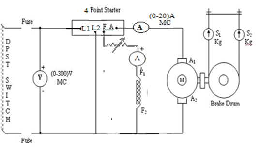
6. The load is then added to the motor gradually and for each load, voltmeter, ammeter, spring balance readings and speed of the motor are noted(Take readings up to rated current of the machine).
7. The motor is then brought to no load condition and field rheostat to minimum position, then switch off the supply.
GRAPH
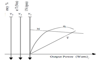
To plotting the performance characteristics take output along X axis and speed, efficiency, load current, torque along Y axis.
RESULT:
CIRCUIT DIAGRAM:
TABULAR COLUMN:
| S. No. | Input Voltage VL (Volts) | If | Ia | In put current IL (amps) | Speed N(rpm) | Spring balance Readings | Torque T(Nm) | Output Power Pout (Watts) | Input Power Pin (watts) | % η | ||||
| S1 (Kg) | S2 (Kg) | S1-S2 (Kg) | ||||||||||||
SAMPLE GRAPH:
EXPERIMENT NO : 6
BRAKE TEST ON DC SERIES MOTOR
AIM:
1) To conduct load test on DC series motor and to plot the following characteristics curves
- Torque Vs Armature current (electrical characteristics)
- Speed Vs Armature current
- Speed Vs Torque (Mechanical characteristics)
- Efficiency Vs output
APPARATUS REQUIRED:
| Sl no | Name of Apparatus | Type | Specification | Qty |
| 1 | Ammeter | |||
| 2 | Voltmeter | |||
| 3 | Rheostat | |||
| 4 | Tachometer | |||
MACHINES DETAILS:
PROCEDURE:
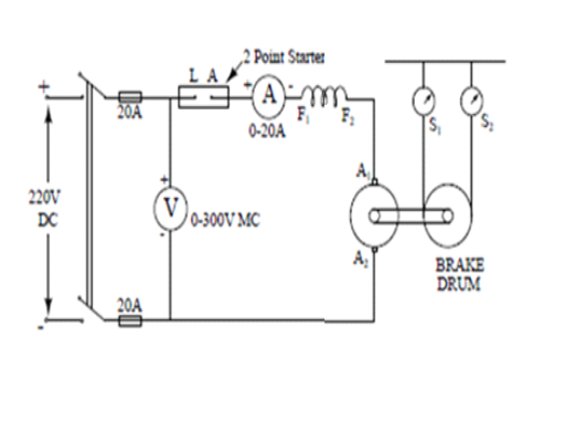
1. Connections are made as per the circuit diagram
2. Before starting, checking the no load condition and keep the armature rheostat should be in maximum position and fild rheostat at minimum position.
RESULT:
Load test on the given series motor is conducted and also plotted the folloing characteristics curves.
- Torque Vs Armature current (electrical characteristics)
- Speed Vs Armature current
- Speed Vs Torque (Mechanical characteristics)
- Efficiency Vs output
CIRCUIT DIAGRAM
TABULAR COLUMN
| S. No. | Input Voltage VL (Volts) | In put current IL (amps) | Speed N(rpm) | Spring balance Readings | Torque T(Nm) | Output Power Pout (Watts) | Input Power Pin (watts) | % η | ||
| S1 (Kg) | S2 (Kg) | S1-S2 (Kg) | ||||||||
Performance curve


Recent Comments