
Load Test on Dc Series Motor
LOAD TEST ON DC SERIES MOTOR
AIM:
1) To conduct load test on DC series motor and to determine the efficiency using mechanical loading arrangement
2) To draw the following characteristics curves
- Torque Vs Armature current (electrical characteristics)
- Speed Vs Armature current
- Speed Vs Torque (Mechanical characteristics)
- Performance curve
APPARATUS REQUIRED:
| Sl no | Name of Apparatus | Type | Specification | Qty |
| 1 | Ammeter | |||
| 2 | Voltmeter | |||
| 3 | Rheostat | |||
| 4 | Tachometer |
MACHINES DETAILS:
THEORY:
Ina series motor the field winding is connected in series with the armature .The field current and the armature current are the same.Series motor is a variable speed motor. If the mechanical load on the motor increases, the armature current also increases. Hence the flux in a series motor increases with increase in armature current.
NαEb/ɸ
Taα ɸ Ia
ɸ α Ia , so Taα Ia2
ie, Starting torque of a series motor will be very high .
ifNαEb/ɸ ,WhenIa is very small speed become dangerously high, so a series motor should never be started without somemechanical load on it, if there is no mechanical load at the time of starting it may develop excessive speed and get damaged due to heavy centrifugal force produced.
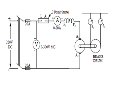
The load test is conducted by applying a spring balance load to brake drum of machine. By tightening the belt over the pulley different load can be applied. The spring balance reading S1 and S2 are noted and the effective radius ‘r’ of the pulley is measured.
If N is the speed of motor, then Torque developed T= (S1-S2)rg Nm
The output power can be calculated as P=2πNT/60 Watts.
Efficiency of the motor=output power/input power.
PRECAUTIONS:
1. DC Series motor should notstart on no load condition.
2. Brake drum should be cooled with water when it is under load.
PROCEDURE:
- Connections are made as per the circuit diagram.
- The precautions checked before starting the experiment.
- A 220 V Dc supply is given to the circuit using two point starter.
- Varying the load (Take readings up to rated current of the machine) by tightening/releasing the belt over the pulley, the meter readings, spring balance reading and speed are noted. After bring the load to initial position, switch of the supply.
FORMULAE USED:
1.Torque(T)=9.81(S1-S2). R
Where, S1, S2→ spring balance readings in kg
R → Radius of brake drums in m
2. Output power (Pout) = 2πNT/60
Where, N=Speed in rpm
T=Torque in Nm
3. In put power (P in)= VL.IL Watts
VL=Input voltage in volts
IL=Input current in Amps
4. % Efficiency =( Pout/Pin)*100
CIRCUIT DIAGRAM
TABULAR COLUMN:
| S. No. | Input Voltage VL (Volts) | In put current IL (amps) | Speed N(rpm) | Spring balance Readings | Torque T(Nm) | Output Power Pout (Watts) | Input Power Pin (watts) | % η | |
| S1 (Kg) | S2 (Kg) | S1-S2 (Kg) |
SAMPLE GRAPH :
RESULT:


Recent Comments