
Load Test on Squirrel Cage Induction Motor
LOAD TEST ON 3−φ SQUIRREL CAGE INDUCTION MOTOR
AIM:
To conduct load test on the given 3-φ squirrel cage induction motor and plot the performance.
APPARATOUS REQUIRED:
| S.No. | Apparatus | Range | Type | Quantity |
| 1 | Ammeter | |||
| 2 | Voltmeter | |||
| 3 | Rheostats | |||
| 4 | SPST Switch | |||
| 5 | Tachometer |
MACHINES DETAILS:
THEORY :
A squirrel cage induction motor essentially consists of a stator and a rotor. The stator is a hollow cylindrical structure with slots on the inner periphery and carries a three phase winding. The winding can be connected in star or delta and is connected across a 3-φ supply. The rotor is also a cylindrical structure with slots on the outer periphery. The slots carry thick Al or Cu bars. These bars are short circuited at both ends by means of end rings. When a 3-φ supply is given to a 3-φ winding displaced by 120◦ in space, a magnetic field of constant magnitude but rotating at synchronous speed is produced. This flux links with the stationary rotor, thus inducing an emf in it. As the rotor circuit is closed, a current flows through it.
The direction of the induced current is such as to oppose the cause producing it. The cause is the relative motion between the stator magnetic field and the rotor. So the rotor starts rotating in the same direction as the stator magnetic field and tries to catch up with it. But practically it is never able to do so. Because if it does so, there would be no relative motion, no emf and hence no torque. Thus an induction motor always runs at a speed slightly less than the synchronous speed. The term
slip is of importance in an induction motor and is defined as An induction motor can never operate at s=0. It always operates between s=0 and s=1(starting).
PRECAUTIONS:
- TPST switch is kept open initially.
- The external resistance in the rotor circuit should be kept at max. value.
PROCEDURE:
- The load on the motor is completely removed by loosening the brake drum.
- The motor is to be always started and stopped at no load, The supply is switched on and the motor is started using a Direct On Line Starter (DOL Starter).
- The readings of the voltmeter, ammeter, wattmeters and spring balance are noted down. The speed is measured using a tachometer.
- The load is then increased in steps, each time noting down all the above readings.
- The experiment is repeated for different values of load currents till the rated current of the machine is reached.
- During the experiment, the machine may get heated up. It is cooled by pouring some water into the brake drum.At low loads,(when pf< 0.5) one of the wattmeters read negative, in such cases, the supply is switched off and the connections to the M and L terminals of the wattmeter are interchanged.
- The meter now reads positive, but it is to be recorded as negative.
- The load on the machine is removed completely and the supply is switched off. The readings are tabulated and the performance characteristics are plotted.
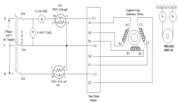
CIRCUIT DIAGRAM
TABULAR COLUMN:
| SL. NO | LOAD CURRENT (A) | LOAD VOLTAGE (V) | W1 | W2 | INPUT POWER (W) W1+W2 | SPEED (N) | SPRING BALANCE READING (Kg) | TORQUE (Nm) | OUTPUT POWER (w) | EFFICIENCY | SLIP | POWER FACTOR |
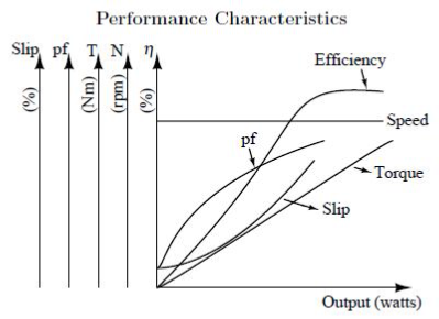
SAMPLE GRAPH :


Recent Comments